Building blocks of a pll, Pll behavior, Types of plls – Altera ALTPLL (Phase-Locked Loop) IP Core User Manual
Page 2
Building Blocks of a PLL
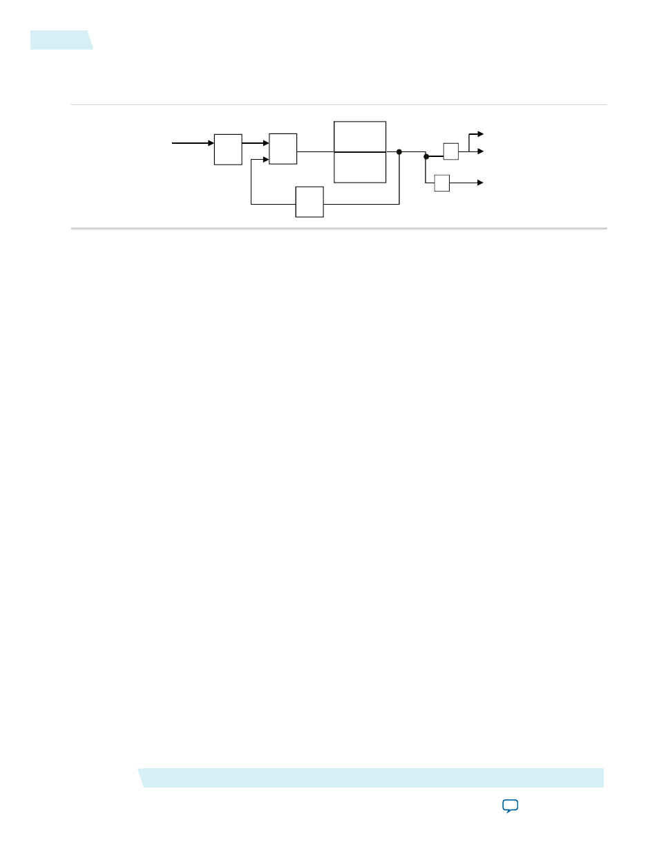
Figure 1: PLL Block Diagram
Feedback
N
Post-Dividers
K
Loop
Filter
& VCO
Charge
Pump
PFD
V
M
FIN
FREF
FVCO
FOUT1
FOUT1
FOUT2
The PLL consists of a pre-divider counter (N counter), a phase-frequency detector (PFD) circuit, a charge
pump, loop filter, a VCO, a feedback multiplier counter (M counter), and post-divider counters (K and V
counters).
The PFD detects the differences in phase and frequency between its reference signal (f
REF
) and feedback
signal (Feedback), controls the charge pump, and controls a loop filter that converts the phase difference to
a control voltage. This voltage controls the VCO.
Based on the control voltage, the VCO oscillates at a higher or lower frequency, which affects the phase and
frequency of the Feedback signal. After the f
REF
signal and the Feedback signal have the same phase and
frequency, the PLL is said to be phase-locked.
Inserting the M counter in the feedback path causes the VCO to oscillate at a frequency that is M times the
frequency of the f
REF
signal. The f
REF
signal is equal to the input clock (f
IN
) divided by the pre-scale counter
(N).
The reference frequency is described by the equation f
REF
= f
IN
/N. The VCO output frequency is f
VCO
= f
IN
× M/N, and the output frequency of the PLL is described by the equation f
OUT
= (f
IN
× M)/(N × K) for the
signals.
PLL Behavior
• PLL lock time—Also known as the PLL acquisition time, PLL lock time is the amount of time required
by the PLL to attain the target frequency and phase relationship after power-up, after a programmed
output frequency change, or after a reset of the PLL. Simulation software does not model a realistic PLL
lock time. Simulation shows an unrealistically fast lock time.
• PLL resolution—The minimum frequency increment value of a PLL VCO. The value is based on the
number of bits in the M and N counter.
• PLL sample rate—The f
REF
sampling frequency required to perform the phase and frequency correction
in the PLL. The PLL sample rate is f
REF
/N.
Types of PLLs
The types of PLL supported by the IP core depend on the device family. Device families typically support
one or two PLL types. For example, the Stratix series supports two types of PLLs, and the Cyclone series
supports only one type. The two PLL types supported within a device family are identical in their analog
portions and differ slightly in the digital portion, for example, more counters on one type than another.
ALTPLL (Phase-Locked Loop) IP Core User Guide
Altera Corporation
ug-altpll
Building Blocks of a PLL
2
2014.08.18