Basic concepts in mstp, Mst region – H3C Technologies H3C S5120 Series Switches User Manual
Page 175

1-10
z
MSTP supports mapping VLANs to spanning tree instances by means of a VLAN-to-instance
mapping table. MSTP can reduce communication overheads and resource usage by mapping
multiple VLANs to one instance.
z
MSTP divides a switched network into multiple regions, each containing multiple spanning trees
that are independent of one another.
z
MSTP prunes a loop network into a loop-free tree, thus avoiding proliferation and endless cycling of
packets in a loop network. In addition, it provides multiple redundant paths for data forwarding, thus
supporting load balancing of VLAN data.
z
MSTP is compatible with STP and RSTP.
Basic Concepts in MSTP
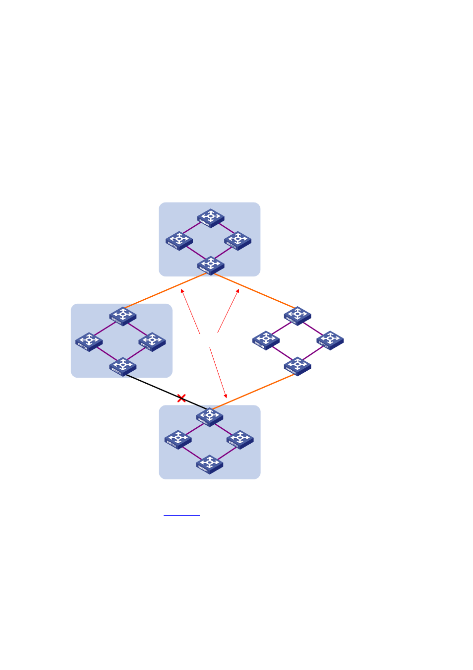
Figure 1-4
Basic concepts in MSTP
CST
Region A0
VLAN 1 mapped to instance 1
VLAN 2 mapped to instance 2
Other VLANs mapped to CIST
Region B0
VLAN 1 mapped to instance 1
VLAN 2 mapped to instance 2
Other VLANs mapped to CIST
Region C0
VLAN 1 mapped to instance 1
VLAN 2 and 3 mapped to
instance 2
Other VLANs mapped to CIST
Region D0
VLAN 1 mapped to instance 1,
B as regional root bridge
VLAN 2 mapped to instance 2,
C as regional root bridge
Other VLANs mapped to CIST
BPDU
BPDU
BPDU
C
D
B
A
Assume that all devices in
are running MSTP. This section explains some basic concepts of
MSTP.
MST region
A multiple spanning tree region (MST region) consists of multiple devices in a switched network and the
network segments among them. These devices have the following characteristics:
z
All are MSTP-enabled,
z
They have the same region name,
z
They have the same VLAN-to-instance mapping configuration,