Configuration procedure – H3C Technologies H3C S5120 Series Switches User Manual
Page 711
1-5
z
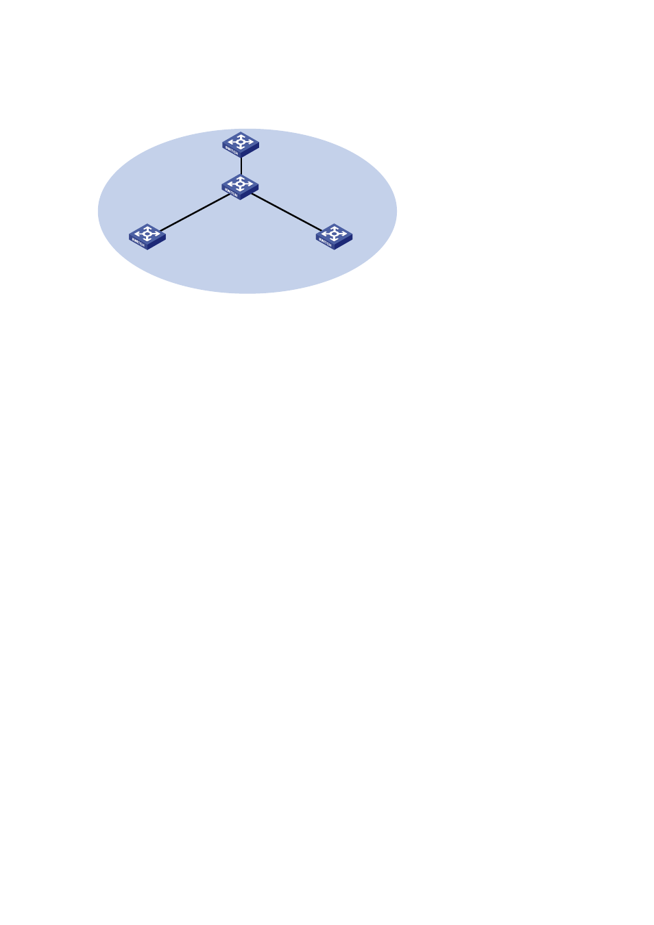
Create a stack, where Switch A is the master device, Switch B, Switch C, and Switch D are slave
devices. An administrator can log in to Switch B, Switch C and Switch D through Switch A to
perform remote configurations.
Figure 1-2 Network diagram for stack management
GE1/0/1
GE1/0/3
SwitchB: Slave device
GE1/0/1
GE1/0/1
SwitchC: Slave device
SwitchD: Slave device
Stack
GE1/0/1
GE1/0/2
SwitchA: Master device
Configuration procedure
1) Configure the master device
# Configure a private IP address pool for the stack on Switch A.
<SwitchA> system-view
[SwitchA] stack ip-pool 192.168.1.1 24
# Configure port GigabitEthernet 1/0/1 as a stack port on Switch A.
[SwitchA] stack stack-port 1 port gigabitethernet 1/0/1
# Configure switch A as the master device.
[SwitchA] stack role master
2) Configure the slave devices
# On Switch B, configure local ports GigabitEthernet 1/0/2, GigabitEthernet 1/0/1, and GigabitEthernet
1/0/3 as stack ports.
<SwitchB> system-view
[SwitchB] stack stack-port 3 port gigabitethernet 1/0/1 gigabitethernet 1/0/2
gigabitethernet 1/0/3
# On Switch C, configure local port GigabitEthernet 1/0/1 as a stack port.
<SwitchC> system-view
[SwitchC] stack stack-port 1 port gigabitethernet 1/0/1
# On Switch D, configure local port GigabitEthernet 1/0/1 as a stack port.
<SwitchD> system-view
[SwitchD] stack stack-port 1 port gigabitethernet 1/0/1
3) Verify the configuration
# Display stack information of the stack members on Switch A.
<stack_0.SwitchA> display stack members
Number : 0
Role : Master
Sysname : stack_0. SwitchA