Own in, Figure 5-3 – H3C Technologies H3C S5120 Series Switches User Manual
Page 365
5-3
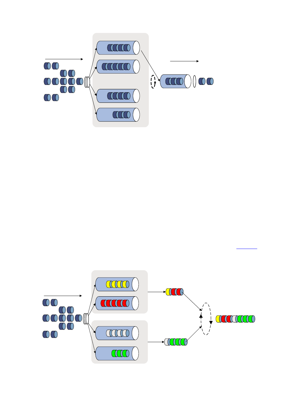
Figure 5-3 Schematic diagram for WRR queuing
Queue 0 Weight 1
Queue 1 Weight 2
Queue 2 Weight 5
Queue 3 Weight 7
Packets to be sent through
this port
Sent packets
Interface
Queue
scheduling
Sending queue
Packet
classification
Assume there are four output queues on a port. WRR assigns each queue a weight value (represented
by w3, w2, w1, or w0) to decide the proportion of resources assigned to the queue. On a 100 Mbps port,
you can configure the weight values of WRR queuing to 50, 25, 25, and 25 (corresponding to w3, w2,
w1, and w0 respectively). In this way, the queue with the lowest priority is assured of 20 Mbps of
bandwidth at least, thus avoiding the disadvantage of SP queuing that packets in low-priority queues
may fail to be served for a long time.
Another advantage of WRR queuing is that while the queues are scheduled in turn, the service time for
each queue is not fixed, that is, if a queue is empty, the next queue will be scheduled immediately. This
improves bandwidth resource use efficiency.
The H3C S5120-SI Switch Series support group-based WRR queuing. You can assign output queues to
WRR queuing group 1 and WRR queuing group 2. The switch uses WRR queuing to schedule queues
in each group according to their weights, and then uses SP queuing to schedule the dequeued packets.
For example, assign queues 0 and 1 to WRR queuing group 1, with the weights 1 and 2 respectively,
and assign queues 2 and 3 to WRR queuing group 2, with the weights 1 and 3 respectively.
shows the scheduling process.
Figure 5-4 Scheduling process of WRR with two WRR queuing groups
Packets to be sent
through this interface
Queue 0 Weight 1
Queue 1 Weight 2
Queue 2 Weight 1
Queue 3 Weight 3
WRR Group1
WRR Group2
SP scheduling
Sending queue