Configuration procedure – H3C Technologies H3C S5120 Series Switches User Manual
Page 291
1-4
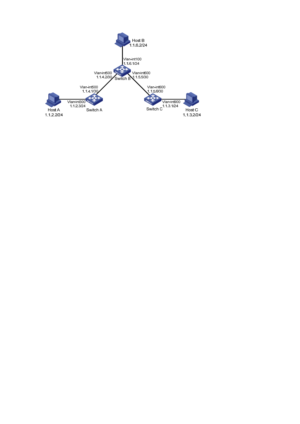
Figure 1-1 Network diagram for static route configuration
Configuration procedure
1) Configuring IP addresses for interfaces (omitted)
2) Configuring static routes
# Configure a default route on Switch A.
<SwitchA> system-view
[SwitchA] ip route-static 0.0.0.0 0.0.0.0 1.1.4.2
# Configure two static routes on Switch B.
<SwitchB> system-view
[SwitchB] ip route-static 1.1.2.0 255.255.255.0 1.1.4.1
[SwitchB] ip route-static 1.1.3.0 255.255.255.0 1.1.5.6
# Configure a default route on Switch C
<SwitchC> system-view
[SwitchC] ip route-static 0.0.0.0 0.0.0.0 1.1.5.5
3) Configure the hosts.
The default gateways for the three hosts A, B and C are 1.1.2.3, 1.1.6.1 and 1.1.3.1 respectively. The
configuration procedure is omitted.
4) Display the configuration.
# Display the IP routing table of Switch A.
[SwitchA] display ip routing-table
Routing Tables: Public
Destinations : 7 Routes : 7
Destination/Mask Proto Pre Cost NextHop Interface
0.0.0.0/0 Static 60 0 1.1.4.2 Vlan500
1.1.2.0/24 Direct 0 0 1.1.2.3 Vlan300
1.1.2.3/32 Direct 0 0 127.0.0.1 InLoop0
1.1.4.0/30 Direct 0 0 1.1.4.1 Vlan500
1.1.4.1/32 Direct 0 0 127.0.0.1 InLoop0
127.0.0.0/8 Direct 0 0 127.0.0.1 InLoop0