Network diagram, Configuration procedure, Controlling web users by source ip addresses – H3C Technologies H3C S5120 Series Switches User Manual
Page 78: Prerequisites
7-6
Network diagram
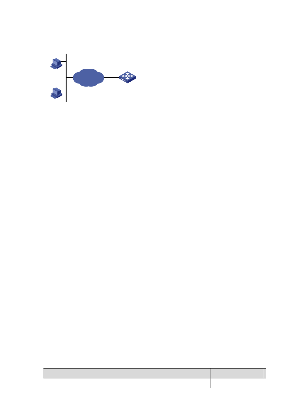
Figure 7-2 Network diagram for controlling SNMP users using ACLs
Switch
10.110.100.46
Host A
IP network
Host B
10.110.100.52
Configuration procedure
# Define a basic ACL.
<Sysname> system-view
[Sysname] acl number 2000 match-order config
[Sysname-acl-basic-2000] rule 1 permit source 10.110.100.52 0
[Sysname-acl-basic-2000] rule 2 permit source 10.110.100.46 0
[Sysname-acl-basic-2000] rule 3 deny source any
[Sysname-acl-basic-2000] quit
# Apply the ACL to only permit SNMP users sourced from the IP addresses of 10.110.100.52 and
10.110.100.46 to access the switch.
[Sysname] snmp-agent community read h3c acl 2000
[Sysname] snmp-agent group v2c h3cgroup acl 2000
[Sysname] snmp-agent usm-user v2c h3cuser h3cgroup acl 2000
Controlling Web Users by Source IP Addresses
The Ethernet switches support Web-based remote management, which allows Web users to access the
switches using the HTTP protocol. By referencing access control lists (ACLs), you can control the
access of Web users to the switches.
Prerequisites
The control policies to be implemented on Web users are decided, including the source IP addresses to
be controlled and the control action, that is, whether to allow or deny the access.
Controlling Web Users by Source IP Addresses
This feature is achieved through the configuration of basic ACLs, the numbers of which are in the range
2000 to 2999. For the definition of ACLs, see ACL Configuration.
Follow these steps to configure controlling Web users by source IP addresses:
To do…
Use the command…
Remarks
Enter system view
system-view
—