Configuring an ospf stub area, Network requirements, Configuration procedure – H3C Technologies H3C SR8800 User Manual
Page 129
113
10.2.1.0/24 O_ASE 150 1 11.2.1.1 GE3/1/1
10.3.1.0/24 O_ASE 150 1 11.2.1.1 GE3/1/1
10.4.1.0/24 O_ASE 150 1 11.2.1.1 GE3/1/1
11.2.1.0/24 Direct 0 0 11.2.1.2 GE3/1/1
11.2.1.2/32 Direct 0 0 127.0.0.1 InLoop0
127.0.0.0/8 Direct 0 0 127.0.0.1 InLoop0
127.0.0.1/32 Direct 0 0 127.0.0.1 InLoop0
5.
Configure summary route 10.0.0.0/8 on Router B and advertise it:
[RouterB-ospf-1] asbr-summary 10.0.0.0 8
# Display the routing table of Router A.
[RouterA] display ip routing-table
Routing Tables: Public
Destinations : 5 Routes : 5
Destination/Mask Proto Pre Cost NextHop Interface
10.0.0.0/8 O_ASE 150 2 11.2.1.1 GE3/1/1
11.2.1.0/24 Direct 0 0 11.2.1.2 GE3/1/1
11.2.1.2/32 Direct 0 0 127.0.0.1 InLoop0
127.0.0.0/8 Direct 0 0 127.0.0.1 InLoop0
127.0.0.1/32 Direct 0 0 127.0.0.1 InLoop0
The output shows that routes 10.1.1.0/24, 10.2.1.0/24, 10.3.1.0/24 and 10.4.1.0/24 are
summaried into one route 10.0.0.0/8.
Configuring an OSPF stub area
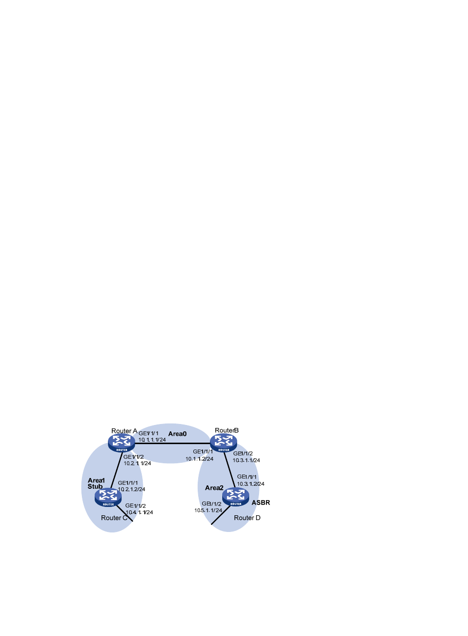
Network requirements
shows an AS is split into three areas, where all routers run OSPF. Router A and Router B act as
ABRs to forward routing information between areas. Router D acts as the ASBR and is enabled to
redistribute static routes.
Configure Area 1 as a Stub area, reducing LSAs to this area without influencing route reachability.
Figure 41 OSPF Stub area configuration
Configuration procedure
1.
Configure IP addresses for interfaces. (Details not shown)