Bgp load balancing configuration example, Network requirements, Configuration procedure – H3C Technologies H3C SR8800 User Manual
Page 261
245
Reply from 9.1.2.1: bytes=56 Sequence=3 ttl=254 time=47 ms
Reply from 9.1.2.1: bytes=56 Sequence=4 ttl=254 time=46 ms
Reply from 9.1.2.1: bytes=56 Sequence=5 ttl=254 time=47 ms
--- 9.1.2.1 ping statistics ---
5 packet(s) transmitted
5 packet(s) received
0.00% packet loss
round-trip min/avg/max = 15/37/47 ms
[RouterC] ping -a 9.1.2.1 8.1.1.1
PING 8.1.1.1: 56 data bytes, press CTRL_C to break
Reply from 8.1.1.1: bytes=56 Sequence=1 ttl=254 time=2 ms
Reply from 8.1.1.1: bytes=56 Sequence=2 ttl=254 time=2 ms
Reply from 8.1.1.1: bytes=56 Sequence=3 ttl=254 time=2 ms
Reply from 8.1.1.1: bytes=56 Sequence=4 ttl=254 time=2 ms
Reply from 8.1.1.1: bytes=56 Sequence=5 ttl=254 time=2 ms
--- 8.1.1.1 ping statistics ---
5 packet(s) transmitted
5 packet(s) received
0.00% packet loss
round-trip min/avg/max = 2/2/2 ms
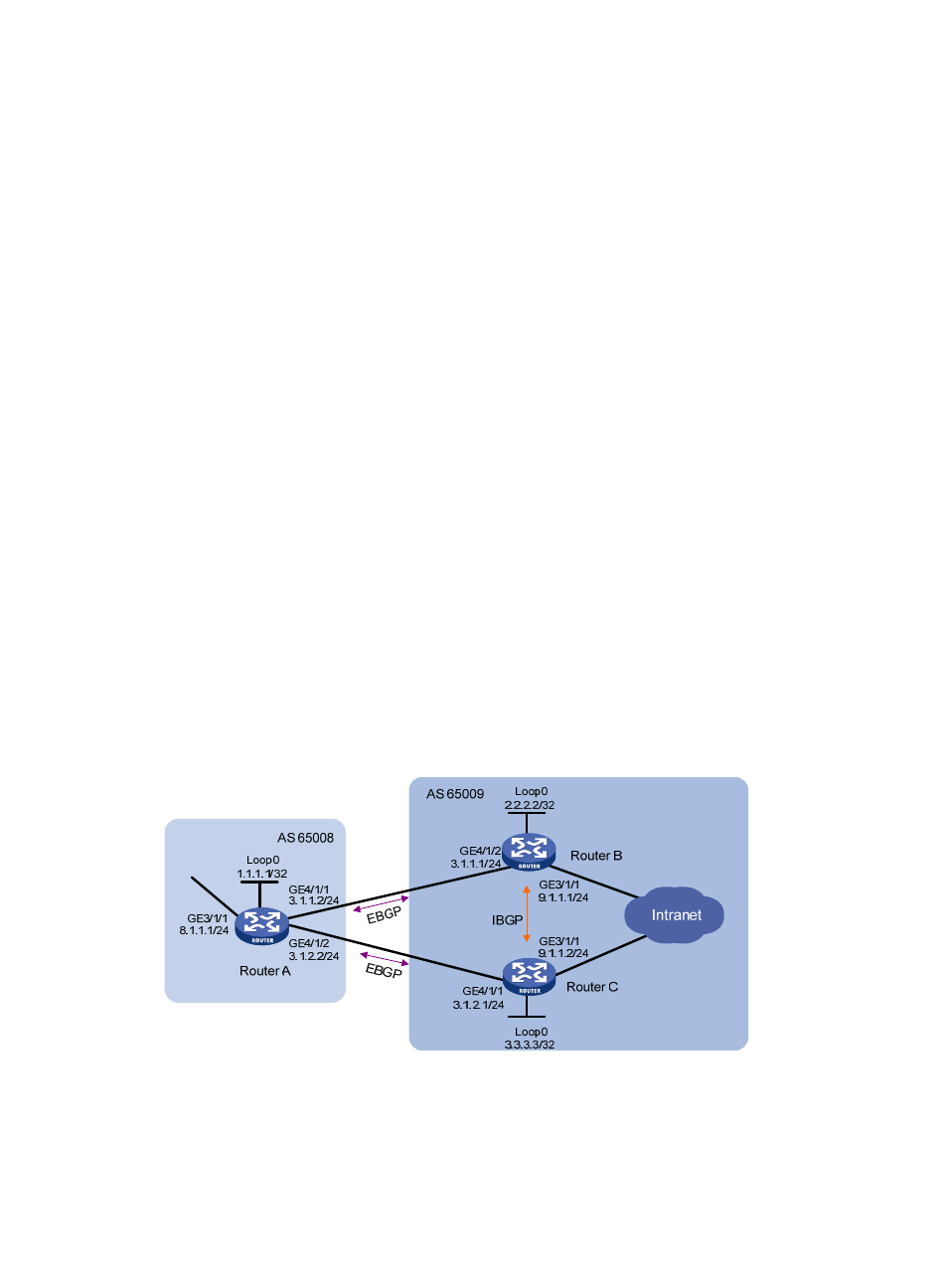
BGP load balancing configuration example
Network requirements
This example describes how to configure BGP load balancing.
As shown in
, all routers run BGP, and Router A resides in AS 65008, Router B and Router C in
AS 65009. Between Router A and Router B, Router A and Router C are EBGP connections, and between
Router B and Router C is an IBGP connection. Two routes are configured on Router A for load balancing.
Figure 92 Network diagram
Configuration procedure
1.
Configure IP addresses for interfaces. (Details not shown)
2.
Configure BGP connections: