Network requirements, Configuration procedure – H3C Technologies H3C SR8800 User Manual
Page 36
20
120.1.1.0/24 Static 60 0 12.1.1.2 GE3/1/1
BFD for static routes configuration example (indirect session)
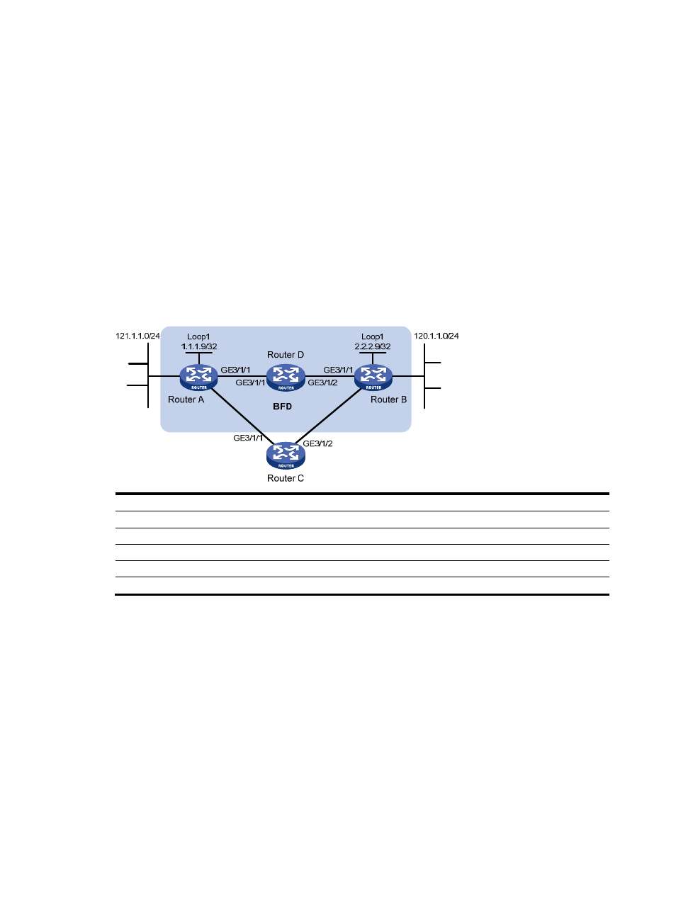
Network requirements
As shown in
, Router A has a route to interface Loopback1 (2.2.2.9/32) on Router B, with the
outbound interface GigabitEthernet 3/1/1. Router B has a route to interface Loopback1 (1.1.1.9/32) on
Router A, with the outbound interface GigabitEthernet 3/1/1. Router D has a route to 1.1.1.9/32, with the
outbound interface GigabitEthernet 3/1/1, and a route to 2.2.2.9/32, with the outbound interface
GigabitEthernet 3/1/2.
Configure a static route to subnet 120.1.1.0/24 on Router A and configure a static route to subnet
121.1.1.0/24 on Router B. Enable BFD for both routes so that when the link between Router A and Router
B through Router D fails, BFD can detect the failure immediately and Router A and Router B can
communicate through Router C.
Figure 5 Network diagram
Device Interface IP
address
Device
Interface
IP address
Router A
GE3/1/1
12.1.1.1/24
Router B
GE3/1/1 11.1.1.2/24
GE3/1/2
10.1.1.102/24
GE3/1/2
13.1.1.2/24
Loop1
1.1.1.9/32
Loop1
2.2.2.9/32
Router C
GE3/1/1
10.1.1.100/24
Router D
GE3/1/1 12.1.1.2/24
GE3/1/2
13.1.1.2/24
GE3/1/2
11.1.1.1/24
Configuration procedure
1.
Configure IP addresses for the interfaces. (Details not shown)
2.
Configure BFD:
# Configure static routes on Router A and enable BFD control packet mode for the static route
through Router D.
<RouterA> system-view
[RouterA] interface loopback 1
[RouterA-LoopBack1] bfd min-transmit-interval 500
[RouterA-LoopBack1] bfd min-receive-interval 500
[RouterA-LoopBack1] bfd detect-multiplier 9
[RouterA-LoopBack1] quit
[RouterA] ip route-static 120.1.1.0 24 2.2.2.9 bfd control-packet bfd-source 1.1.1.9
[RouterA] ip route-static 120.1.1.0 24 GigabitEthernet 3/1/2 10.1.1.100 preference
65
GE3/1
/2
GE3/1/2