Configuring ospf virtual links, Network requirements, Configuration procedure – H3C Technologies H3C SR8800 User Manual
Page 138
122
Configuring OSPF virtual links
Network requirements
•
In
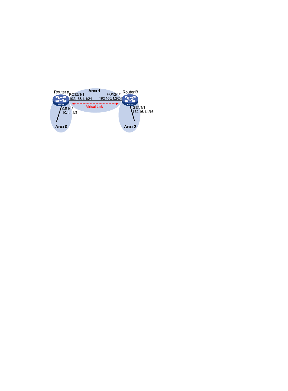
, Area 2 has no direct connection to Area 0, the backbone, and Area 1 acts as the
Transit Area to connect Area 2 to Area 0 via a virtual link between Router A and Router B.
•
After configuration, Router A can learn routes to Area 2.
Figure 44 Network diagram
Configuration procedure
1.
Configure IP addresses for interfaces. (Details not shown)
2.
Configure OSPF basic functions:
# Configure Router A.
<RouterA> system-view
[RouterA] ospf 1 router-id 1.1.1.1
[RouterA-ospf-1] area 0
[RouterA-ospf-1-area-0.0.0.0] network 10.0.0.0 0.255.255.255
[RouterA-ospf-1-area-0.0.0.0] quit
[RouterA-ospf-1] area 1
[RouterA-ospf-1-area-0.0.0.1] network 192.168.1.0 0.0.0.255
[RouterA-ospf-1-area-0.0.0.1] quit
# Configure Router B.
<RouterB> system-view
[RouterB] ospf 1 router-id 2.2.2.2
[RouterB-ospf-1] area 1
[RouterB-ospf-1-area-0.0.0.1] network 192.168.1.0 0.0.0.255
[RouterB-ospf-1-area-0.0.0.1] quit
[RouterB-ospf-1] area 2
[RouterB–ospf-1-area-0.0.0.2] network 172.16.0.0 0.0.255.255
[RouterB–ospf-1-area-0.0.0.2] quit
[RouterB-ospf-1] quit
# Display OSPF routing information on Router A.
[RouterA] display ospf routing
OSPF Process 1 with Router ID 1.1.1.1
Routing Tables
Routing for Network
Destination Cost Type NextHop AdvRouter Area
10.0.0.0/8 1 Stub 10.1.1.1 1.1.1.1 0.0.0.0
192.168.1.0/24 1562 Stub 192.168.1.1 1.1.1.1 0.0.0.1