Configuring ospf frr, Network requirements, Configuration procedure – H3C Technologies H3C SR8800 User Manual
Page 144
128
[RouterA] ospf 1
[RouterA-ospf-1] filter-policy 2000 import
[RouterA-ospf-1] quit
# Display the OSPF routing table of Router A.
[RouterA] display ip routing-table
Routing Tables: Public
Destinations : 10 Routes : 10
Destination/Mask Proto Pre Cost NextHop Interface
3.1.1.0/24 O_ASE 150 1 10.2.1.2 GE3/1/2
3.1.2.0/24 O_ASE 150 1 10.2.1.2 GE3/1/2
10.1.1.0/24 Direct 0 0 10.1.1.1 GE3/1/1
10.1.1.1/32 Direct 0 0 127.0.0.1 InLoop0
10.2.1.0/24 Direct 0 0 10.2.1.1 GE3/1/2
10.2.1.1/32 Direct 0 0 127.0.0.1 InLoop0
10.3.1.0/24 OSPF 10 4 10.1.1.2 GE3/1/1
10.4.1.0/24 OSPF 10 13 10.2.1.2 GE3/1/2
127.0.0.0/8 Direct 0 0 127.0.0.1 InLoop0
127.0.0.1/32 Direct 0 0 127.0.0.1 InLoop0
The route to 10.5.1.1/24 is filtered out.
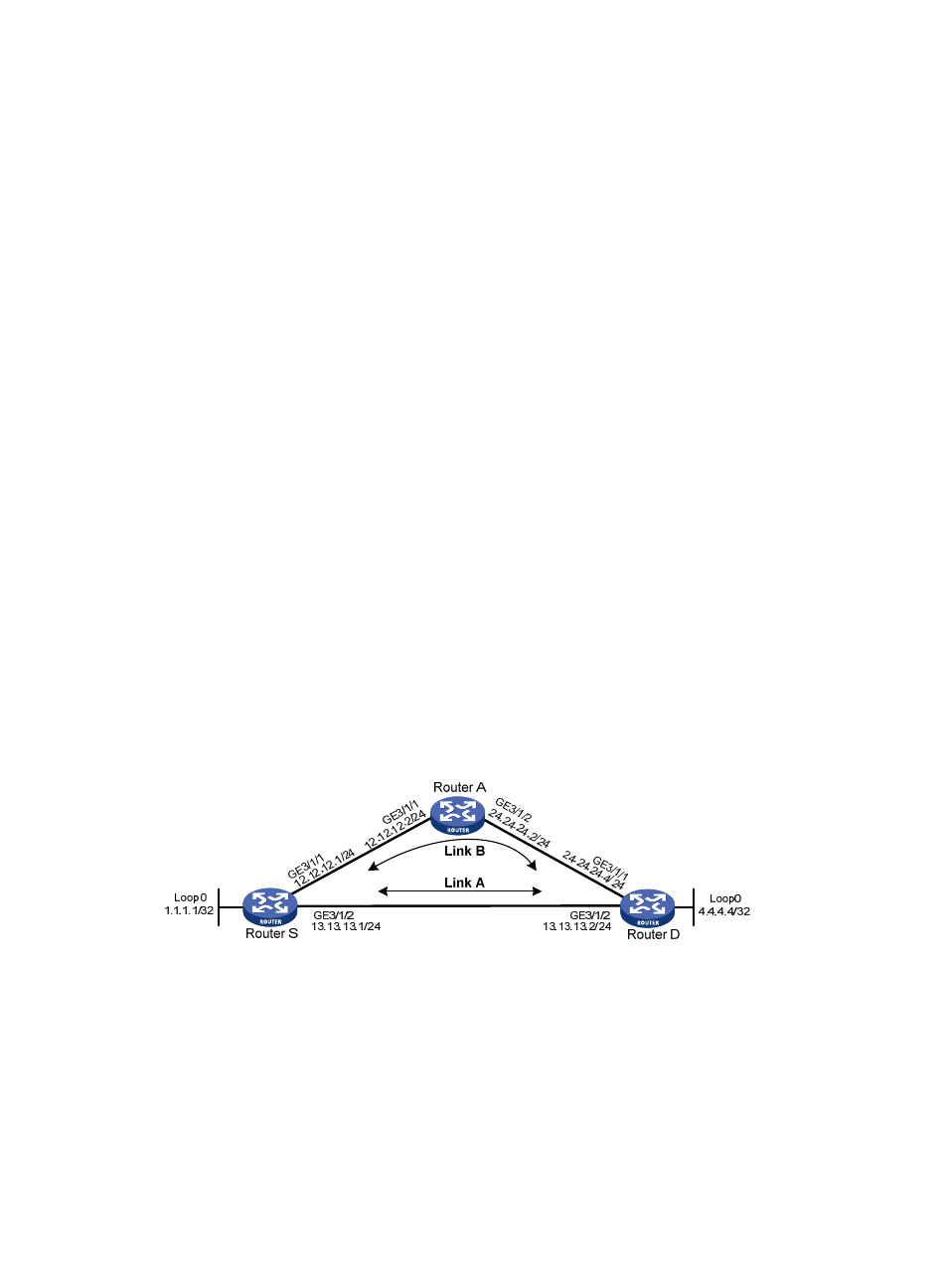
Configuring OSPF FRR
Network requirements
Router S, Router A, and Router D belong to the same OSPF domain as illustrated in
. Configure
OSPF FRR so that when the link between Router S and Router D fails, traffic can be switched to Link B
immediately.
Figure 47 Network diagram
Configuration procedure
1.
Configure IP addresses for the interfaces on each router and configure OSPF:
Follow
to configure the IP address and subnet mask of each interface on the routers.
(Details not shown)
Configure OSPF on the routers, ensuring that Router S, Router A, and Router D can communicate
with each other at Layer 3. (Details not shown)
2.
Configure OSPF FRR: