Configuring bfd for ospf, Network requirements – H3C Technologies H3C SR8800 User Manual
Page 146
130
Summary Count : 1
Destination: 4.4.4.4/32
Protocol: OSPF Process ID: 1
Preference: 10 Cost: 1
NextHop: 13.13.13.2 Interface: GigabitEthernet3/1/2
BkNextHop: 12.12.12.2 BkInterface: GigabitEthernet3/1/1
RelyNextHop: 0.0.0.0 Neighbor : 0.0.0.0
Tunnel ID: 0x0 Label: NULL
State: Active Adv Age: 00h01m27s
Tag: 0
# Display route 1.1.1.1/32 on Router D. You can find the backup next hop information.
[RouterS] display ip routing-table 1.1.1.1 verbose
Routing Table : Public
Summary Count : 1
Destination: 1.1.1.1/32
Protocol: OSPF Process ID: 1
Preference: 10 Cost: 1
NextHop: 13.13.13.1 Interface: GigabitEthernet3/1/2
BkNextHop: 24.24.24.2 BkInterface: GigabitEthernet3/1/1
RelyNextHop: 0.0.0.0 Neighbor : 0.0.0.0
Tunnel ID: 0x0 Label: NULL
State: Active Adv Age: 00h01m27s
Tag: 0
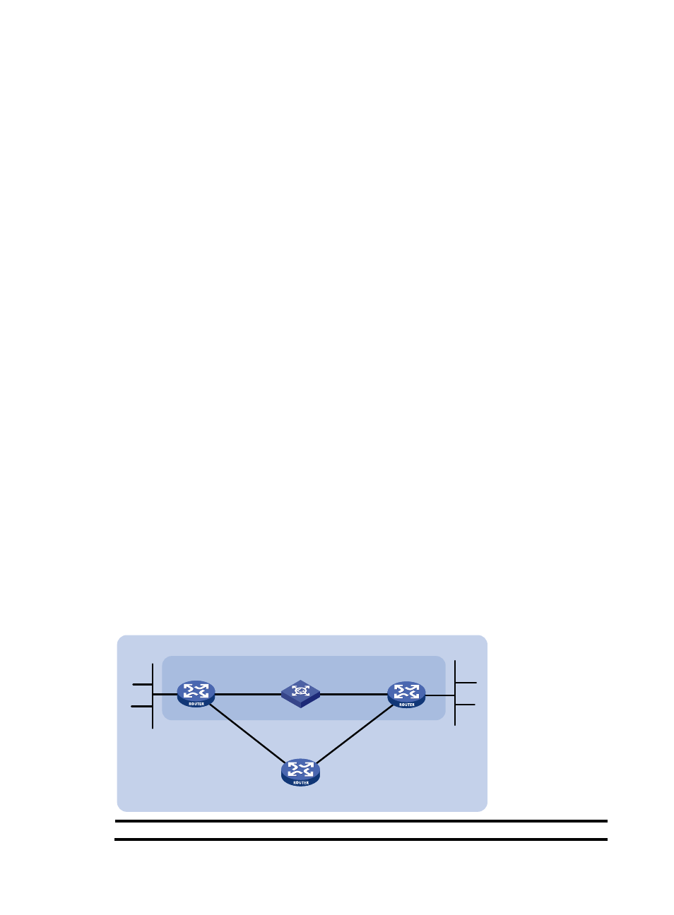
Configuring BFD for OSPF
Network requirements
As shown in
:
•
OSPF is enabled on Router A, Router B and Router C so that they are reachable to each other at the
network layer.
•
After the link over which Router A and Router B communicate through a Layer 2 switch fails, BFD can
quickly detect the failure and notify OSPF of the failure. Router A and Router B then communicate
through Router C.
Figure 48 Network diagram
Device
Interface
IP address
Device
Interface
IP address
GE3/1/1
GE
Router A
Router B
BFD
L 2 Switch
Area 0
Router C
GE
GE
GE
GE
120.1.1.0/ 24
121.1.1.0/ 24
3/1/1
3/1/2
3/1/2
3/1/1
3/1/2