Appendix f: mariner™ machine interface – Hypertherm HTA Rev 6.00 Install Guide User Manual
Page 207
Appendix E: Voyager™ II Machine Interface
195
Appendix F: Mariner™ Machine
Interface
The Mariner™ Shape Cutting Control is designed with all machine interface connections passing
through the pedestal mount at the base of the enclosure. Motion and I/O are supported via the fiber
optic communication ring of the SERCOS Interface™.
The information contained in this section is intended to provide the basic information for connection of
the Mariner™ Shape Cutting Control to the cutting table. Each machine interface will vary slightly
based on the cutting table configuration and features.
Operation and maintenance of automated equipment involves potential hazards. Personnel should
take precautions to avoid injury. This equipment should only be opened by trained service personnel.
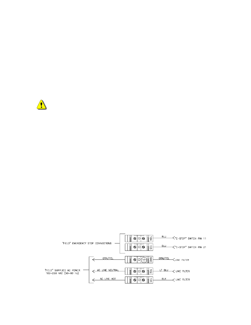
AC Input Pinout
TB connector
Description
101
110VAC or 220VAC Input ( Hot )
102
110VAC or 220VAC Input ( Neutral )
AC Power Ground
Recommended Wire
14 AWG or greater
E-Stop
The E-stop Switch provides normally open contacts rated at 20VAC/500mA minimum to 250VAC/6A
maximum.
TB connector
Description
103 Contact
Closure
104 Contact
Closure
Diagram Location Din-02