Error code troubleshooting – 3 of 10 -13 – Hypertherm HPR260 Manual Gas Preventive Maintenance Program Rev.5 User Manual
Page 157
MAINTENANCE
HPR260 Auto Gas
Instruction Manual
5-13
Error code troubleshooting – 3 of 10
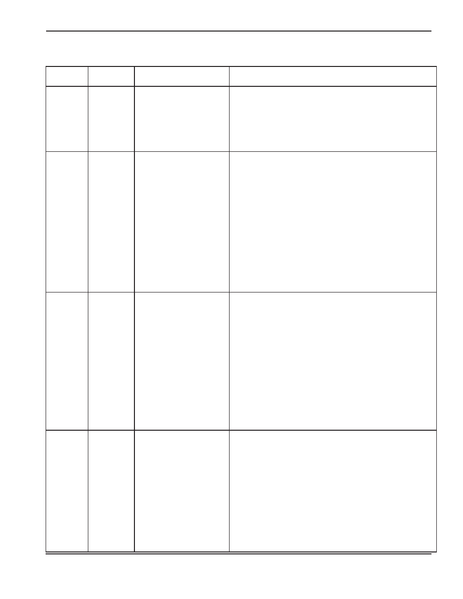
Error code
number
Name
Description
Corrective action
045
High plasma
gas pressure
Plasma gas pressure over
upper limit of 7.58 bar
(110 psi).
1. Verify gas supply pressure settings.
2. Verify gas regulator settings on gas console with cut chart.
3. See Setting the supply regulators (Installation section).
4. Solenoid at off-valve is not opening. Verify power to valves,
disconnect plasma and shield hoses exiting off-valve.
If pressures decrease a valve is not functioning or no power
to the valve.
046
Low line
voltage
Line voltage is close to or
less than the lower limit of
102 VAC (120 VAC -15%).
The normal lower limit for
operation is
108 VAC (120 VAC -10%).
1. Verify input-line voltage. Voltage needs to be within 10 % of
nominal (120 VAC).
2. Verify fuses on PCB2.
3. Verify 120 VAC voltage on plug J2.4, pins 3 and 4 on PCB2.
4. Verify voltage on receptacle J2 on PCB2. Should be
approximately 1.65 VDC between pins 1 and 2.
5. If AC voltage on J2.4, pins 3 and 4, is greater than 108 VAC
and DC voltage on J2 is less than 1.485 VDC, replace
PCB2.
6. If AC voltage on J2.4, pins 3 and 4, is greater than 108 VAC
and DC voltage on J2 is also greater than 1.485 VDC, verify
the DC voltage to J3.201 on PCB3. It should equal the
voltage reading on J2. If the DC voltage readings are the
same and the wiring passes continuity tests, replace PCB3.
047
High line
voltage
Line voltage is close to or
greater than the upper limit
of 138 VAC
(120 VAC +15%).
The normal upper limit for
operation is 132 VAC (120
VAC +10%).
1. Verify input-line voltage. Voltage needs to be within 10 % of
nominal (120 VAC).
2. Verify fuses on PCB2.
3. Verify 120 VAC voltage on plug J2.4, pins 3 and 4 on PCB2.
4. Verify voltage on receptacle J2 on PCB2. Should be
approximately 1.65 VDC between pins 1 and 2.
5. If AC voltage on J2.4, pins 3 and 4, is less than 132 VAC
and DC voltage on J2 is greater than 1.815 VDC, replace
PCB2.
6. If AC voltage on J2.4, pins 3 and 4, is less than 132 VAC
and DC voltage on J2 is less than 1.815 VDC , verify the DC
voltage to J3.201 on PCB3. It should equal the voltage
reading on J2. If the DC voltage readings are the same and
the wiring passes continuity tests, replace PCB3.
048
CAN error
An error occurred with the
CAN communications
between the power supply
and the gas console.
1. Verify that cable number 5 (power supply-to-gas console
control cable) is not damaged and is properly connected to
PCB3 and to the rear of the gas console.
2. Verify that cable number 6 (power supply-to-gas console
power cable) is not damaged and is properly connected
inside the power supply and to the rear of the gas console.
3. Verify that D1 (+5 VDC) and D2 (+3.3 VDC) are illuminated
on PCB2 inside the gas console. These LEDs indicate
power to PCB2.
4. If power is present at PCB2 and PCB3 and both gas
console cables are good, then PCB2 or PCB3 has failed.
Use the CAN tester to verify which board needs to be
replaced.
5