Stainless steel, H35 and n, Plasma / n – Hypertherm HPR260 Manual Gas Preventive Maintenance Program Rev.5 User Manual
Page 281: Shield 130 a cutting, Marking metric english
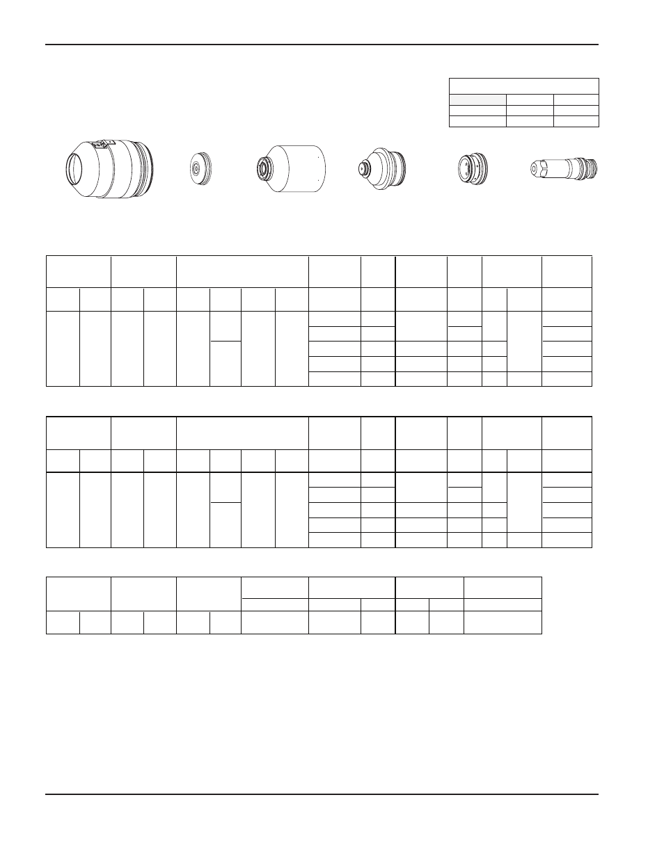
APPENDIX C – CUT CHARTS FOR PREVIOUS SYSTEM REVISIONS
c-12
HPR260 Auto Gas
Instruction Manual
Stainless steel
H35 and N
2
Plasma / N
2
Shield
130 A Cutting
220198
220173
220307
220304
220179
220197
Note: This process produces a smoother, shinier cut edge with less dross and greater cut angle variation than
the 130A, N
2
/N
2
process. Edge color is more silver than the H35/N
2
process.
Flow rates – lpm/scfh
H35
N
2
Preflow
0 / 0
97 / 205
Cutflow
13 / 28
71 / 150
Plasma Shield Plasma Shield Plasma Shield
Mix
Gas 1
Mix
Gas 2
mm
Volts
mm factor %
seconds
6
150
0.3
10
153
0.3
12
160
7.0
0.5
15
168
7.6
0.8
20
176
7.7
180
1.3
Plasma Shield Plasma Shield Plasma Shield
Mix
Gas 1
Mix
Gas 2
in
Volts
in
factor %
seconds
1/4
150
0.3
3/8
153
0.3
1/2
160
0.280
0.5
5/8
168
0.300
0.8
3/4
176
0.310
180
1.3
mm
in
mm/min
N
2
N
2
10
10
10
10
2.5
0.100
6350
Material
Thickness
Arc
Voltage
Torch-to-
Work
Distance
75
38
32
3.8
3.5
3.0
Select
Gases
Set
Preflow
Set
Cutflow
H35
N
2
19
60
27
18
1835
6.0
Pierce
Delay Time
mm
mm/m
Cutting
Speed
Initial Pierce
Height
200
1195
875
670
4.3
305
Material
Thickness
Arc
Voltage
Torch-to-
Work
Distance
Select
Gases
Set
Preflow
Set
Cutflow
H35
N
2
19
60
200
50
75
38
32
18
0.120
70
0.240
Pierce
Delay Time
in
ipm
Cutting
Speed
Initial Pierce
Height
Marking
Metric
English
27
0.140
30
0.150
25
0.170
15
Torch-to-Work
Distance
Select
Gases
Set
Preflow
Set
Cutflow
Amperage
Amps
ipm
Volts
130
250
18
Marking
Speed
Arc
Voltage