Phase-loss detection test -50, Phase-loss detection test – Hypertherm HPR260 Manual Gas Preventive Maintenance Program Rev.5 User Manual
Page 194
MAINTENANCE
5-50
HPR260 Auto Gas
Instruction Manual
3
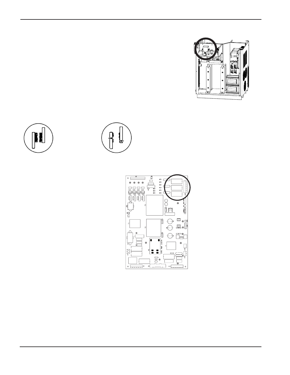
Phase-loss detection test
1. Turn OFF all power to the system and remove the cover from CON1.
2. Inspect the condition of the 3 contacts for excessive wear. If one or more of the contacts are worn excessively,
replace CON1 and restart the system. If the error remains, perform the following steps.
3. Test the fuses F5, F6, and F7 on the power
distribution board (PCB2). If any of the fuses
are blown, replace PCB2.
4. Remove J2.8 from PCB2 and place a jumper between pins 1 and 2 on the cable connector.
a. Make a test cut. If the phase-loss error continues, verify wiring between J2.8 on PCB2 and J3.302 on PCB3 by
verifying the continuity between
– J2.8 pin1 to J3.302 pin14
– J2.8 pin2 to J3.302 pin15.
b. If the wiring is OK, replace PCB3. If any wiring is damaged, repair or replace any damaged wires.
c. If the phase-loss error goes away while the jumper is on J2.8, make another cut and measure the phase-to-
phase voltage across the fuses F5, F6, and F7. The voltage should be 220 VAC +/-15%. If 1 of the 3 voltage
readings is less than 187 VAC, check the contacts to the contactor, and check for loose connections between
the power cord, contactor, power transformer, and the chopper.
D23
D12
D26
D31
D32
D33
D3
D25
D1
D7
D5
D2
D35
OK
Excessive wear