Hardware description, Product brief description – Niveo Professional NGSME16T2H User Manual
Page 17
Chapter 1: Product Overview
Product Overview
NGSME16T2H User Manual | 17
Hardware Description
This section mainly describes the hardware of Full L2 Management Network Switch
and gives a physical and functional overview on the certain switch.
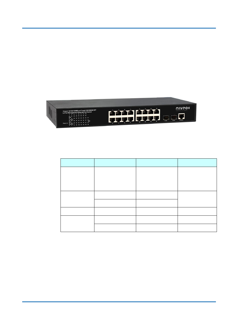
Front Panel
The front panel of the L2 management switch consists of 16 10/100/1000 Base-TX
RJ-45 ports and 2 gigabit uplink SFP ports. The LED Indicators are also located on
the front panel.
LED Indicators
The LED Indicators present real-time information of systematic operation status. The
following table provides description of LED status and their meaning.
LED
Color / Status
Description
No. of LEDs
Power
Amber On
Power on
Power
10/100/1000M
Green On
Link Up
16
Green Blinking
Data Activating
PoE
Amber On
PD is connected
16
SFP
Green On
linked to Power Device
17~18
Green Blinking
Data Activating
17~18
Rear Panel
The rear panel of the Web Smart PoE Switch contains 2 ventilation fans, a power
switch, and a IEC 60320 plug for power supply.