4 cables, 1 rs-232c interface cables – Yaskawa MP920 Communications Module User Manual
Page 126
6 217IF Module
6.4.1 RS-232C Interface Cables
6-10
6.4
Cables
This section explains the cable specifications for communications using the 217IF Module.
6.4.1
RS-232C Interface Cables
1. The power system, control system, and electrical system, as well as the transmission system, must
be wired separately.
2. There are two D-sub 9-pin (CN1, CN2) connectors for the RS-232C interface on the 217IF Module.
3. The maximum length of the RS-232C cable is 15 meters. This cable should be as short as possible.
4. The RS-232C interface of the 217IF Module is not isolated. A malfunction may sometimes occur
due to noise from the connected terminals. If noise is a problem, use a shielded cable or a modem to
reduce the noise.
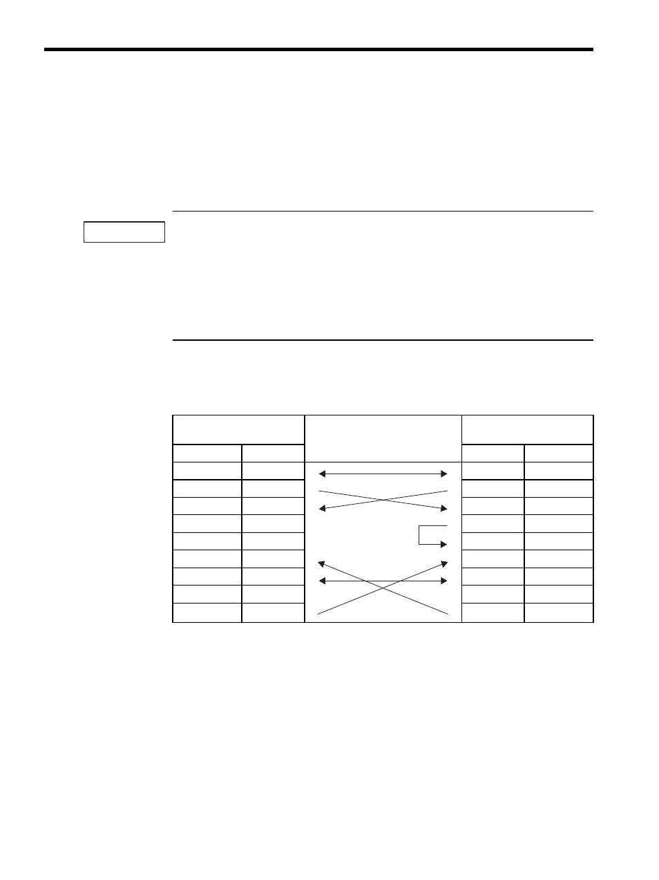
The following table shows the 217IF RS-232C transmission line connections of 217IF Mod-
ule.
Table 6.4 217IF RS-232C Transmission Line Connections
MP920 217IF (CN1, CN2)
Cable Connection and Signal
Direction
Remote Station
(D-sub 25-pin)
Signal Name
Pin No.
Pin No.
Signal Name
FG
1
1
FG
SD (TXD)
2
2
SD (TXD)
RD (RXD)
3
3
RD (RXD)
RS
4
4
RS
CS (CTS)
5
5
CS (CTS)
DR (DSR)
6
6
DSR (DR)
SG
7
7
SG
CD
8
8
CD
ER (DTR)
9
20
DTR (ER)
IMPORTANT