3 setting the logical port numbers, 1 setting the mpe720 logical port numbers – Yaskawa MP920 Communications Module User Manual
Page 61
4.3 Setting the Logical Port Numbers
4-13
4
4.3
Setting the Logical Port Numbers
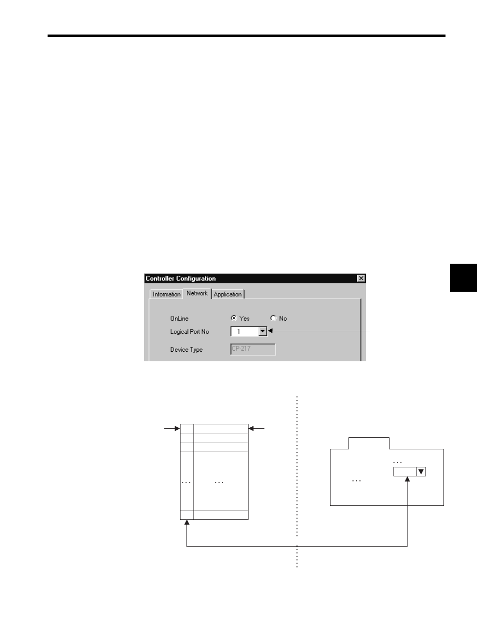
This section explains the logical port number settings.
4.3.1
Setting the MPE720 Logical Port Numbers
Up to 16 logical ports can be registered for the communications process. The logical port to
be used must be specified when engineering a Machine Controller using the MPE720.
The logical port to be used can be set for each Machine Controller and is normally set when
registering a new Machine Controller under the File Manager. (Refer to 2.2.4 Creating New
PLC Folders in the MP900/MP2000 Series Machine Controller Programming Software
MPE720 User’s Manual.)
The following window will be displayed when registering a new PLC folder or opening the
property window for an existing PLC folder. Open the Network Tab Page.
Set the Logical Port No. box in this window to the logical port number to be used.
This number corresponds
to the Logical Port No. in
the Communications Pro-
cess Window.
Serial
CP-215
CP-218
1
2
3
16
Port type
Communications process
Logical port allocation example
Network
1
Onlile specification
Logical port number
MPE720
PLC folder property example
Logical port
number
Logical port number selection