3 data format – Yaskawa MP920 Communications Module User Manual
Page 182
7 218IF Module
7.7.3 Data Format
7-36
7.7.3
Data Format
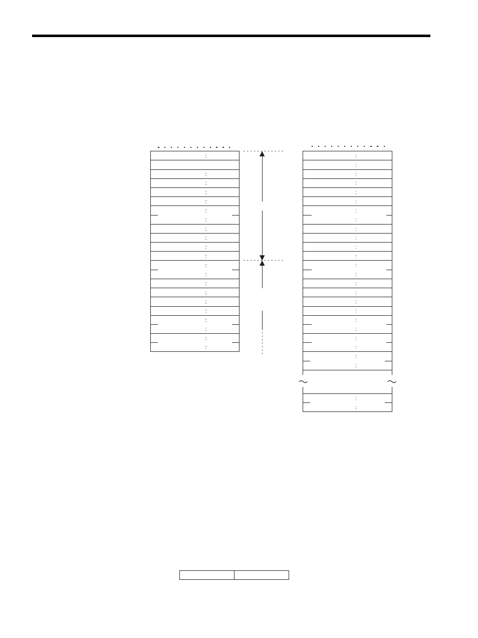
The following diagram shows the data format when the 10 words of data from holding regis-
ters 0 to 9 are read by the SFC09 Holding Register Read (Extended) command, which is one
of the Extended MEMOBUS commands.
7.7.4
Precautions on Creating Data Using a Personal Computer
Using Personal Computer as a Master
MEMOBUS Command Data
• Set the identification number each time communications are performed, using the fol-
lowing data order: 000
→ 00ff → 000.
• Specify 0 for the destination channel.
• Specify 0 for the source channel.
• When the remote station has more than one CPU, set the CPU number as follows:
Note: Destination CPU No.: Specify the CPU number of the Machine Controller.
Source CPU No.: Set to 0.
Command Type
Identification No.
Destination channel
Source channel
Not used
Not used
Not used
Not used
Not used
Not used
8
0
0× 11
0×00
0×00
0×00
0×00
0×00
0×00
0×00
0×00
0×16 (L)
0×00
Data length
Length
0×08
0×00
MFC
SFC
CPU No.
Not used
0×20
0×09
0×00
0×00
0×00
0×0A
0×00
0×00
000
001
002
003
004
005
006
007
008
009
00A
00B
00C
00D
00E
00F
010
011
012
013
014
015
8
0
0×19
0×00
0×00
0×00
0×00
0×00
0×00
0×00
0×00
0×28
Length
0×1A
0×00
MFC
SFC
CPU No.
0×20
0×09
0×00
0×00
0×0A
Data (MW0)
0×00
000
001
002
003
004
005
006
007
008
009
00A
00B
00C
00D
00E
00F
010
011
012
013
014
015
0×00
Data (MW1)
016
017
Data (MW9)
026
027
218 header
Extended
MEMOBUS
packet
Command Type
Identification No.
Destination channel
Sourece channel
Not used
Not used
Not used
Not used
Not used
Not used
Number of registers
Reference No.
Not used
Number of references
(L)
(H)
(H)
(H)
(L)
(L)
(L)
(L)
(H)
(H)
(H)
(H)
(H)
(L)
(L)
(L)
(L)
Data length
MEMOBUS Command
MEMOBUS Respones
7
4 3
0
Bit
Dest. CPU No.
Source. CPU No.