Cn3 rs-485 cable – Yaskawa MP920 Communications Module User Manual
Page 298

Appendix D Wiring Communications
D.1.1 Connection Methods
D-6
CN3 RS-485 Cable
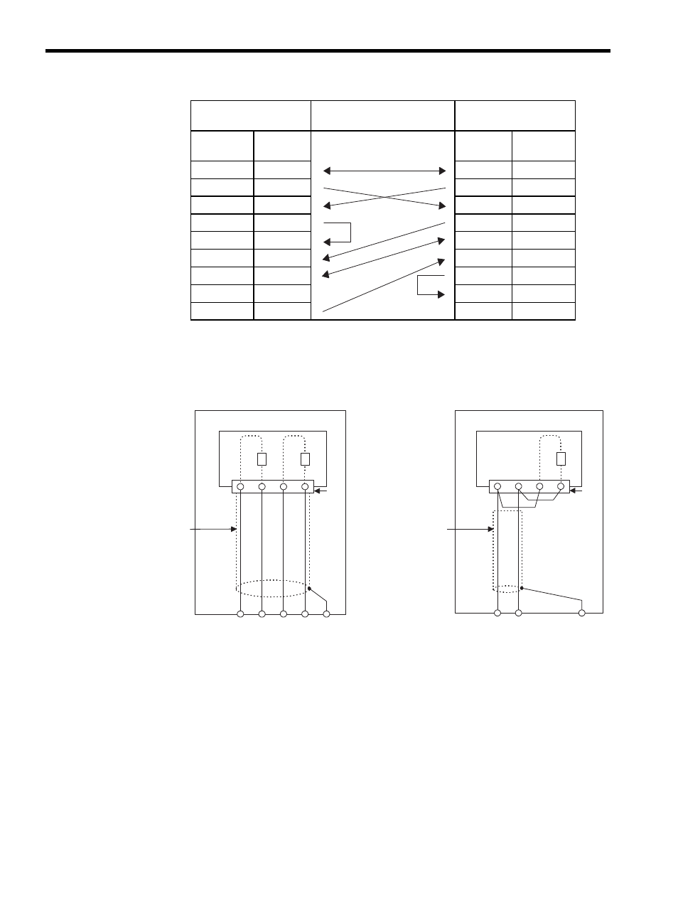
The following figure shows RS-485 transmission line connection examples for 217IF Mod-
ule of the MP920.
Fig. D.3 217IF RS-485 Transmission Line Connection Examples
• The terminating resistance at the end station of the transmission line must be connected.
Shield treatment is required at each intermediate station of the transmission line.
Follow the CN3 wiring shown in 6.4.2 RS-422/485 Interface Cables.
MP920 217IF
(CN1)
Cable Connections and
Signal Directions
PC/AT or Compatible
Computer
Signal
Name
Pin No.
Pin No.
Signal
Name
FG
1
1
FG
SD(TXD)
2
2
SD(TXD)
RD(RXD)
3
3
RD(RXD)
RS
4
4
RS
CS(CTS)
5
5
CS
DR(DSR)
6
6
DSR(DR)
SG
7
7
SG
CD
8
8
CD
ER(DTR)
9
9
RTR(ER)
RX-
RX+
TX-
TX+
RD-
RD+
SD-
SD+
1
2
6
7
120
Ω
120
Ω
CN3
Es
MP920 217IF
In-panel twisted-
pair cable
YS-1PEV-SB:
3P
× 0.3 mm
2
In-panel twisted-
pair cable
YS-1PEV-SB:
1P
× 0.3 mm
2
TX-
TX+
SRD- SRD-
1
2
6
7
120
Ω
CN3
Es
MP920 217IF