6 modem-to-modem connection, 1 system configuration, 2 cable specifications – Yaskawa MP920 Communications Module User Manual
Page 225
Advertising
8 Example Communications Module Applications
8.6.1 System Configuration
8-34
8.6
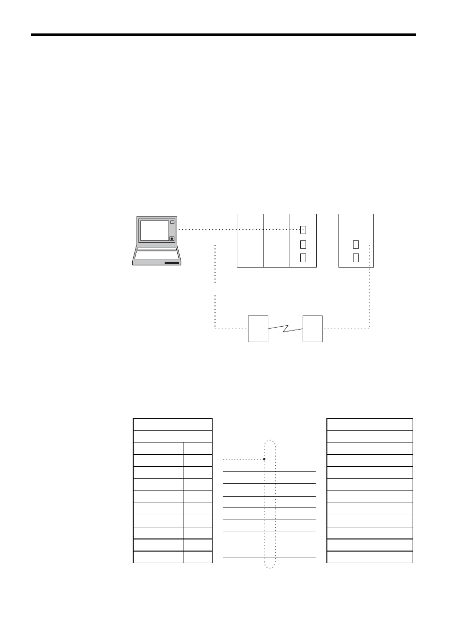
Modem-to-Modem Connection
This section explains MEMOBUS Master/Slave communications with two modems.
8.6.1
System Configuration
The standard serial port (Port 1) of an MP930 located a distance away from the 217IF Mod-
ule is configured as a modem-to-modem system.
The engineering environment is provided by connecting the MPE720 Programming Device
to the CN1 port of the 217IF.
8.6.2
Cable Specifications
217IF Module
↔ Modem
MP930
↔ Modem Connection Cables
MP930
MP920
PS-01
CPU-01
217IF
Engineering
MPE720
MEMOBUS
RS-232C
Modem
Modem
217IF Module
Modem
D-sub 9-pin
D-sub 9-pin
Signal Name
Pin No.
Pin No.
Signal Name
FG
1
1
FG
TXD
2
2
TXD
RXD
3
3
RXD
RTS
4
4
RTS
CTS
5
5
CTS
DSR
6
6
DSR
SG
7
7
SG
N.C.
8
8
N.C.
DTR
9
9
DTR
Advertising