Cp-215 repeater-tc cable connections – Yaskawa MP920 Communications Module User Manual
Page 300
Appendix D Wiring Communications
D.1.1 Connection Methods
D-8
CP-215 Repeater-TC Cable Connections
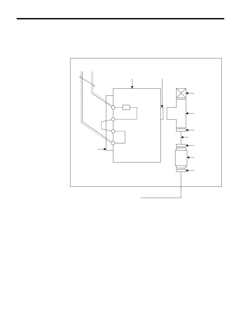
The following figure shows a CP-215 Repeater-TC transmission line connection example.
Fig. D.5 CP-215 Repeater-TC Transmission Line Connection Example
• Connect the in-panel twisted-pair cable (YS-IPEV-SB, 1P
× 0.3 mm
2
, manufactured by
Fujikura Corporation) equipped with an MR-8LM(G) connector to the CN1 transmission
connector on the Repeater.
• Connect pins 8 and 1 of the CN1 transmission connector on the Repeater to SRD+ and
SRD-, respectively.
• Fit a T-connector onto the CN3 transmission connector (BNC connector) on the Repeater,
and connect it to a 3C-2V in-panel coaxial cable equipped with a BNC connector.
• If the Repeater is located at the end of the transmission line, short-circuit pins 4 and 5 of
the CN1 to connect the internal 75
Ω terminating resistance.
1
4
5
8
75
Ω
SRD+
SRD-
215IF in-panel cable
Terminator
CP-215 Repeater-TC
CN1
MR-8LM (G)
CN3: BNC
T-connector
Terminator
BNC
In-panel coaxial
cable 3C-2V
BNC
Conversion
Adapter T-0298
F-connector