Cn3 cables – Yaskawa MP920 Communications Module User Manual
Page 203
8 Example Communications Module Applications
8.2.2 Cable Specifications
8-12
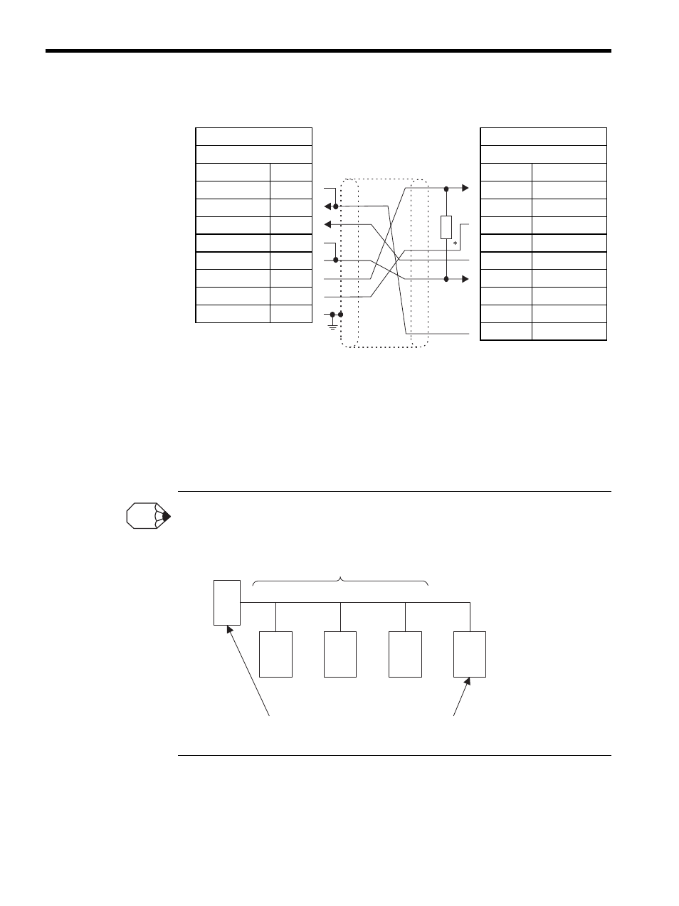
CN3 Cables
* Terminating resistance: 120
Ω
Note: 1. OMRON PLC Models:
C200H-LK202-V1
C500-LK201-V1
C120-LK202-V1
2. Connect the cable so that the terminating resistance for the 217IF
Module is connected.
If the terminating resistance cannot be inserted in the Module, mount 120
Ω.terminating resistance at
the end of the transmission line outside the Module. Insert the terminating resistance in the stations at
both ends of the transmission line. Do not insert it in the intermediate stations.
217IF
OMRON PLC
MR 8-pin
D-sub 9-pin
Signal Name
Pin No.
Pin No.
Signal Name
RXR
4
1
RD B
RX (-)
1
2
N.C.
RX (+)
2
3
SG
TXR
5
4
N.C.
TX (-)
6
5
SD B
TX (+)
7
6
RD A
SG
8
7
FG
SH
3
8
N.C.
9
SD A
Shield
FG
INFO
Intermediate stations
Stations (at both ends) in which the terminating resistance is connected