Setting procedure – Yaskawa MP920 Communications Module User Manual
Page 56
4 Communications Process
4.2.2 CP-215 Communications Port Settings
4-8
* 2. When the CP-215PC/AT Card is model 90000 (87215-90000-S01),
be sure that the jumper lead connecting CH0 and CH1 and the DIP
switch (SW1) are set as follows:
Pin 3: ON
Pin 4: OFF
Jumper lead: Has been cut
When the Card is model 90001 (87215-90001-S01), there is no
jumper lead. Set the DIP switch (SW1) to the following values:
Pin 3: OFF
Pin 4: ON
Setting Procedure
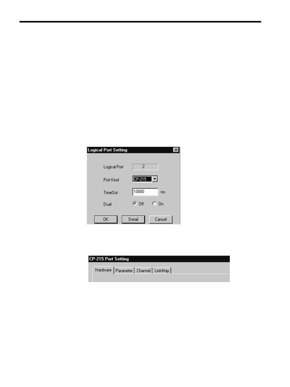
Use the following procedure to set a CP-215 communications port.
1. Select CP-215 under Port Kind on the Logical Port Setting Window and click the Detail
button.
2. The CP-215 Port Setting Window will be displayed when the Detail button is clicked.
Four tabs will be displayed. Set the CP-215 parameters on the Hardware, Parameter, and
Channel Tabs in that order. No settings are required on the Link Map Tab.
a) Hardware Tab Page
Set the operating conditions for the CP-215PC/AT Card installed in the Programming
Device.
• Physical No. (Physical port No.)
Set the I/O port number. Set this to 1 if there is only one CP-215PC/AT Card. If
more than one CP-215PC/AT Card is to be used, allocate ports 2, 3, and 4 in that
order.
• IRQ (Interrupt level)
Select an unused hardware interrupt number on the Programming Device being
used.