L8: drive protection, Refer to l8-01 – Yaskawa AC Drive Z1000 AC Drive HVAC Fan User Manual
Page 116
n
L6-03: Torque Detection Time 1
Determines the time required to trigger an alarm or fault after exceeding the level in L6-02.
No.
Name
Setting Range
Default
L6-03
Torque Detection Time 1
0.0 to 10.0 s
10.0 s
n
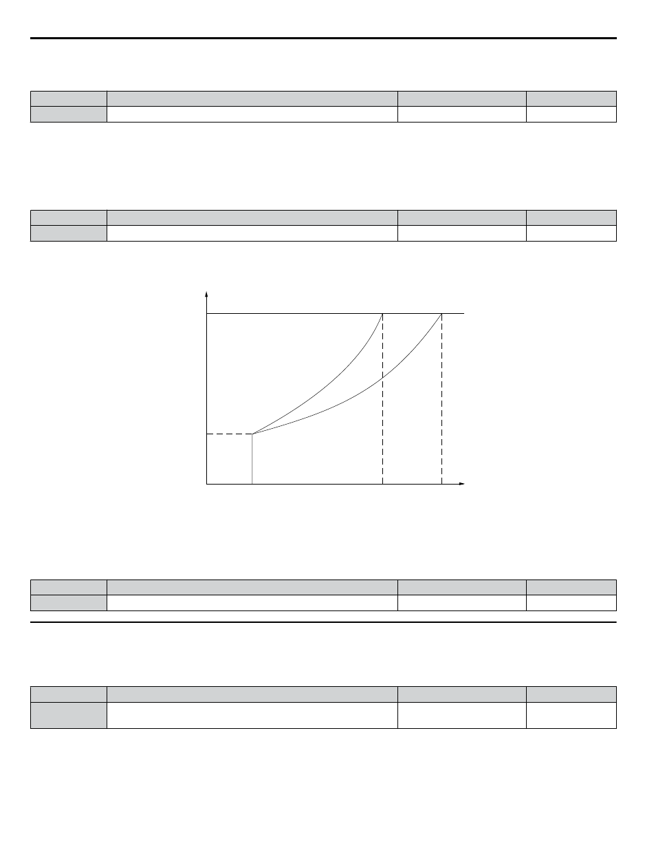
L6-13: Motor Underload Protection Selection
Sets Motor Underload Protection (UL6) based on motor load and determines whether the level of L6-02 refers to fbase or
fmax.
Selects the operation of underload detection UL6. Underload is detected when the output current falls below the underload
detection level defined by L6-14 and L2-02.
No.
Name
Setting Range
Default
L6-13
Motor Underload Protection Selection
0, 1
0
Setting 0: Fbase Motor Load Enabled
Setting 1: Fmax Base Motor Load Enabled
UL Detection Level
L6-02
(0 to 300%)
0
Fmin
Fbase
1/f
Fmax
Output
Frequency
L6-14
Motor Underload
Protection at Fmin
Figure 1.70 Motor Underload Protection
n
L6-14: Motor Underload Protection Level at Minimum Frequency
Sets the UL6 detection level at minimum frequency by percentage of drive rated current
No.
Name
Setting Range
Default
L6-14
Motor Underload Protection Level at Minimum Frequency
0 to 300%
15%
u
L8: Drive Protection
n
L8-01: Internal Dynamic Braking Resistor Protection Selection (ERF type)
Selects the dynamic braking resistor protection when using an optional heatsink mounted braking resistor (ERF type, 3% ED).
No.
Name
Setting Range
Default
L8-01
Internal Dynamic Braking Resistor Protection Selection (ERF type)
0, 1
Determined by
o2-04
Setting 0: Disabled
Disables braking resistor protection. Use this setting for any dynamic braking option other than the Yaskawa ERF-type resistor.
Setting 1: Enabled
Enables protection for Yaskawa ERF-type resistors.
1.8 L: Protection Functions
116
YASKAWA ELECTRIC SIEP YAIZ1U 03A YASKAWA AC Drive – Z1000 Programming Manual