Yaskawa AC Drive Z1000 AC Drive HVAC Fan User Manual
Page 293

Loop Gain
PI Proportional Gain (AO 4) and PI Integral Time (AO 5) are the gain and integral time parameters used by the drive. The PI
loop is structured differently than the Metasys loop. Refer to the User Manual section on PID for information on how the PI
loop functions.
Reading and Resetting Faults
The Fault Monitor (BI 4) and Drive Ready Monitor (BI 3) show the current status of the drive. The Fault Code (AI 10) contains
for descriptions of the fault codes. The drive faults can be reset through the Fault Reset
Command (BO 4). The Fault Reset Command is only available when the Run Forward Command and the Run Reverse
Command are both OFF.
n
Cable Loss Configuration and Behavior
This section describes the configurable cable loss feature of the drive. This feature offers a user maximum flexibility in
determining drive response to a loss of communication.
Drive Behavior at Loss of Communication
The drive can be configured to respond to an interval without receipt of a message in one of the following methods:
• Continue at last speed
• Continue at last speed with alarm
• Continue at preset speed
• Ramp to Stop with EF0 fault
• Coast to Stop with EF0 fault
• Emergency Stop with EF0 fault
Metasys N2 I/O
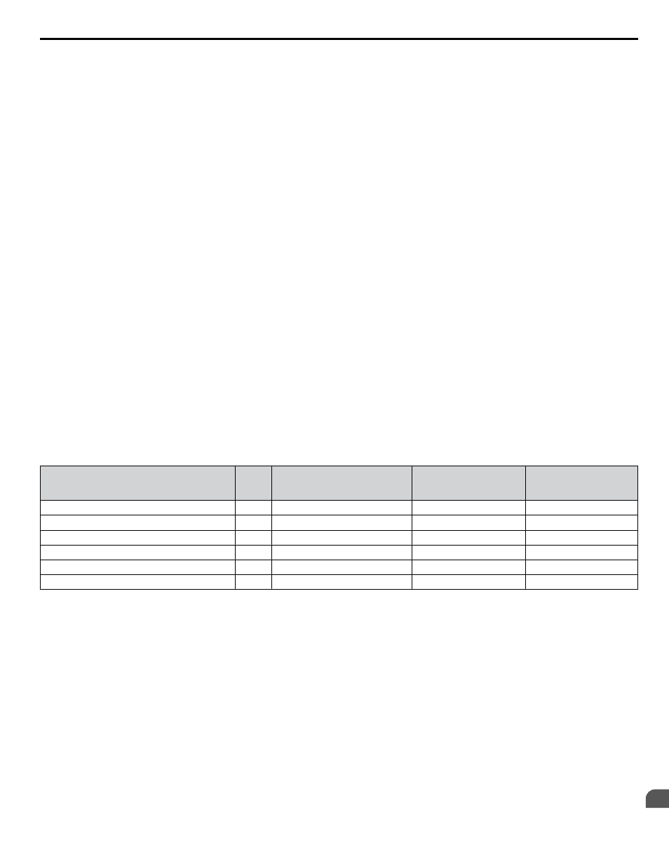
Three Metasys N2 outputs are used to select the desired behavior:
• AO 21 – Cable Loss Timeout
• AO 22 – Cable Loss Speed
• BO 11 – Communication Fault
Table D.2 Cable Loss Behavior Summary
Behavior
H5-04
Cable Loss Timeout
(AO 21)
Cable Loss Speed
(AO 22)
Communication Fault
Enable
(BO 11)
Decelerate to stop (stop time in C1-02) EF0 fault
0
Timeout Interval
X
On
Coast to stop EF0 fault
1
Timeout Interval
X
On
Emergency stop (stop time in C1-09) EF0 fault
2
Timeout Interval
X
On
Continue at last speed
3
0
X
X
Continue at last speed with alarm
3
Timeout Interval
X
On
Continue at preset speed with alarm
4
Timeout Interval
Preset speed
On
Note:
1. Communication must first be established and then lost for these features to function as described. If a drive is powered-up without a
cable connected or with the master controller offline, a communications timeout does not occur.
2. For modes that describe the drive running after a communications timeout, a run command must have been issued (BO 1 = ‘On’ or BO
2 = ‘On’) prior to loss of communications. For safety purposes, the drive will not automatically restart from a stopped condition. If a
user requires the drive to restart automatically, additional external wiring is required to accomplish this (consult factory).
Upon expiration of the communications timeout interval, the FAULT LED lights and remains lit until communication is
restored.
Continue at Last Speed
In this mode, Cable Loss Timeout (AO 21) is set to 0, disabling the cable loss feature. The other two settings Cable Loss Speed
(AO 22) and Communication Fault Enable (BO 11) are ignored. If communication is lost, the drive simply maintains its last
commanded state. The drive will not display an alarm or fault to indicate it has lost communication. This behavior can also
be achieved by setting parameter H5-04 to “3”. The drive will display an alarm and continue running. For this specific condition,
the Communication Fault Enable (BO 11) must be enabled and Cable Loss Timeout (AO 21) should be set to a value other
than 0.
D.5 Drive Operations by N2
YASKAWA ELECTRIC SIEP YAIZ1U 03A YASKAWA AC Drive – Z1000 Programming Manual
293
D
Metasys N2 Communications