6 expansion card with devicenet interface, 6wiring, 8 expansion cards – Pilz PMCprimo DriveP.01/AA0/4/0/0/208-480VAC User Manual
Page 170
6.8
Expansion cards
6
Wiring
Pilz GmbH & Co. KG, Felix-Wankel-Straße 2, 73760 Ostfildern, Germany
Telephone: +49 711 3409-0, Telefax: +49 711 3409-133, E-Mail: [email protected]
6-66
6.8.6
Expansion card with DeviceNet interface
Expansion card with DeviceNet interface
6-
][Verdr_DeviceNet_protego_D
When installing and wiring please refer to the “DeviceNet Specification,
Volume I, II, Version 2.0”, published by ODVA. This contains information
on:
`
Cable selection
`
Cable routing
`
Shielding
`
Bus connectors
`
Bus termination
`
Runtimes
Correct wiring:
`
Stub lines of 0 ... 6 m are permitted on each device.
`
Branches within stub lines are permitted.
`
Voltage to the devices can be supplied via the bus
INFORMATION
Please note:
The signal lines on the first and last subscribers should use con-
nectors fitted with terminating resistors in accordance with the
“DeviceNet Specification, Vol I, Chapter 9” (from Version 2.0,
1997): 121 Ohm, 1% metal film, 1/4 Watt.
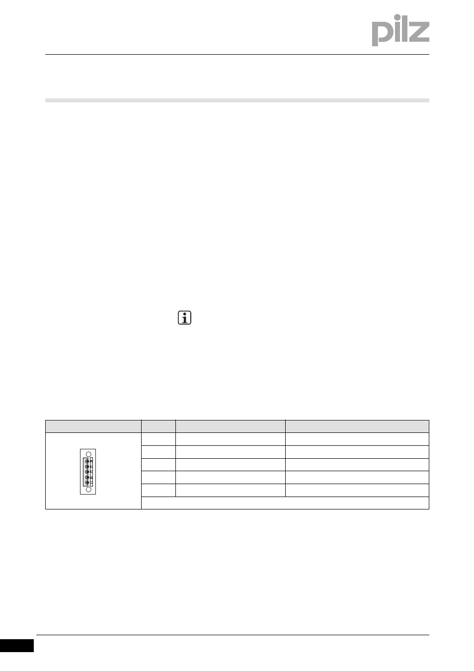
Connector pin assignment
Connector X15
Pin
Designation
Description
1
V-
Supply voltage (-)
2
CAN_L
DeviceNet connection (low signal)
3
SHIELD
Cable shield connection
4
CAN_H
DeviceNet connection (high signal)
5
V+
Supply voltage (+)
5-pin Combicon plug-in connector in accordance with the DeviceNet specification
X15 1 2 3 4 5