2 fault condition, 4function description, 5 switch on/switch off behaviour – Pilz PMCprimo DriveP.01/AA0/4/0/0/208-480VAC User Manual
Page 88
4.5
Switch on/switch off behaviour
4
Function Description
Pilz GmbH & Co. KG, Felix-Wankel-Straße 2, 73760 Ostfildern, Germany
Telephone: +49 711 3409-0, Telefax: +49 711 3409-133, E-Mail: [email protected]
4-56
4.5.2
Fault condition
Fault condition
4-
][Funktion_Ein_Aus_Fehler
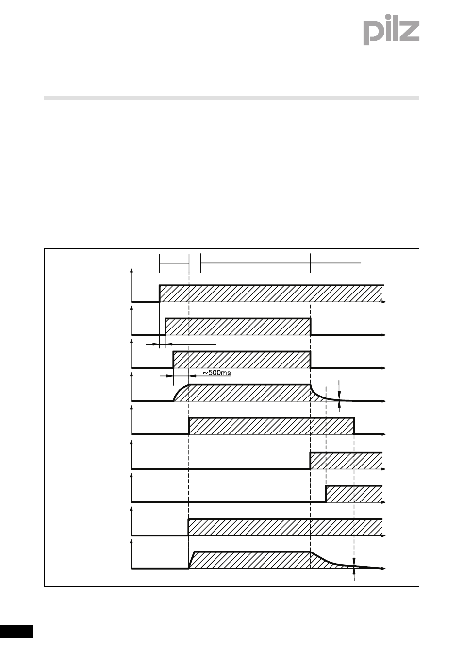
The behaviour of the servo amplifier always depends on the current set-
ting of various parameters (e.g. ACTFAULT, VBUSMIN, VEL0, STOP-
MODE, see commissioning software's online help).
The diagram illustrates the start-up procedure and the sequence of the
servo amplifier's internal control system in the event of a failure of one
or more phases of the mains voltage, when the standard parameters are
set.
`
F16/F19 = Error messages for mains-BTB/input phase
`
F05 = Error message for undervoltage)
Fig. 4-18:
Switching on and off under fault conditions
24 V
X4/1
BTB/RTO
X3B/14,15
L1,L2,L3
X0
Interm. circuit
X8
HW-ENABLE
X3A/1
Motor
speed
Enable output
stages
(internal)
Boot-Time
U
F16 / F19
U
U
U
U
n
t
t
t
t
t
t
t
t
U
VEL0
5
Start
Standard mode
Mains fault
t
3 % VBUSMIN
F05