1 designating pue/dcie data, Designating pue/dcie data – RLE FMS V.1.13 User Manual
Page 109
rletech.com
FMS User Guide
109
3
Web Interface Configuration
3.4.26.1 Designating PUE/DCiE Data
1
Before you can generate the PUE/DCiE data, you need to know where to tell the FMS to
find the raw kW readings. The Modbus registers for this information should already be
configured. On the FMS interface, go to Configuration > Modbus/SNMP Slave Units.
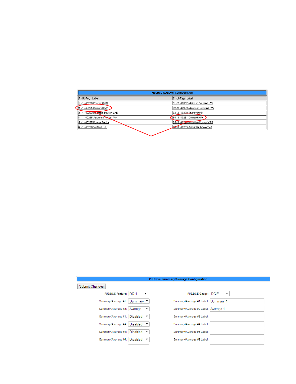
2
Click the appropriate link to access the range of Registers where your devices are located.
Write down the index numbers of the kW-related Modbus registers. You’ll need to enter
these index numbers on the PUE/DCiE Configuration page.
Figure 3.44
Gather Modbus Register Information
3
On the FMS interface, return to the to Configuration>PUE/DCiE/Summary/Average
screen.
4
At the top of the PUE/DCiE/Summary/Average Configuration page, you’ll see a drop down
menu to enable or disable the PUE/DCiE feature. Select an option as follows to begin the
setup:
♦
DC1 - generate one PUE/DCiE value
♦
DC2 - generate two PUE/DCiE values
♦
DC1+2 - generate two PUE/DCiE values and a summary and/or average of those values
5
You can view PUE/DCiE information on the main FMS page in two ways - either as
statistics, or as statistics and a gauge. The FMS can generate a Java-based gauge graphic on
its home page that allows you to see a graphical representation of either your PUE or your
DCiE value. If you’d like to display this gauge, select either PUE or DCiE from the drop
down menu next to the PUE/DCiE Gauge field. If you leave this setting disabled, only
statistics will display on the FMS home page.
Figure 3.45
Enable PUE/DCiE and Designate Gauge Behavior
Modbus Registers - kW Data