2 expansion card “a” input configuration, Expansion card “a” input configuration, Figure 3.8 – RLE FMS V.1.13 User Manual
Page 54
54
FMS User Guide
800.518.1519
3
Web Interface Configuration
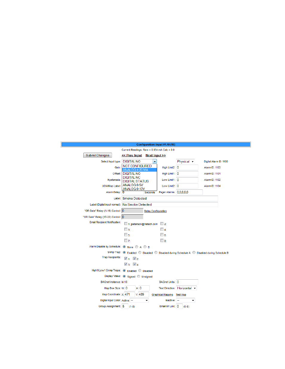
3.4.1.2 Expansion Card “A” Input Configuration
Expansion Card A contains 12 inputs, configurable as analog 4-20mA, 0-5V, 0-10V(analog 0-
5V and 0-10V require additional jumper configuration) or digital NO (cannot be configured
as NC), plus 8 form C relay outputs.
While units will vary depending on individual configurations, inputs for Expansion Card A are
typically numbered 1.1-1.12, 2.1-2.12, etc.
This page will be displayed when configuring an input on an Expansion Card A. It is identical
to the FMS Main Board Input Configuration page—see
3.4.1.1, “Main Card - Input Channels
—with the following exceptions:
♦
The Expansion Card “A” does not except common ground digital inputs. Therefore, the
option for Individual Ground Type (digital input only) is removed.
♦
Analog 0-5VDC and Analog 0-10VDC options are added to the Input Type. The Expansion
Card “A” accepts analog inputs individually configurable through internal jumpers, as
4-20mA, 0-5VDC or 0-10VDC.
Figure 3.8
Expansion Card A Configuration Page