10 expansion card a connections, Expansion card a connections – RLE FMS V.1.13 User Manual
Page 32
32
FMS User Guide
800.518.1519
2
Getting Started
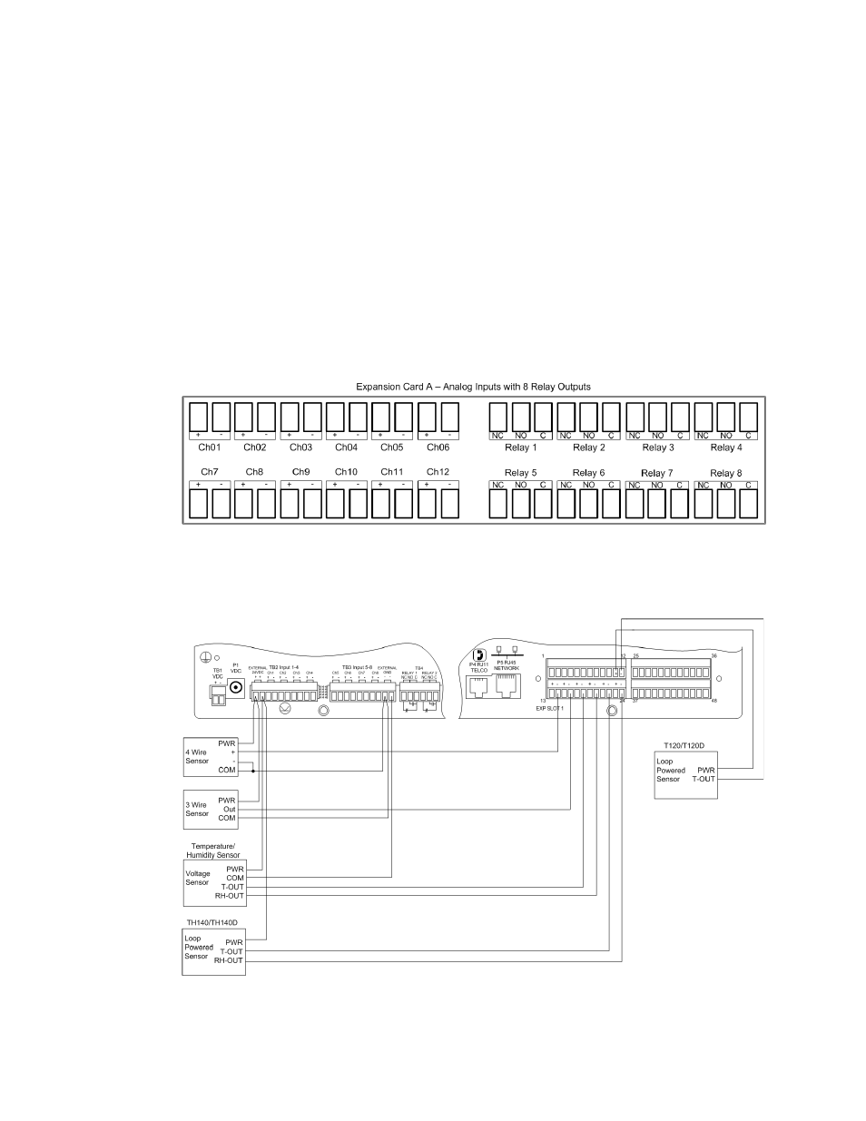
2.2.10 Expansion Card A Connections
A sticker identifying the expansion cards as A or C is located on each Expansion Card. The
following wiring diagrams show the Expansion Card in slot 1. However, the Expansion Card
may be in Slot 2, 3 or 4 based on the FMS configuration. The I/O for each card type appears on
the back of the FMS for reference during field wiring; see
and
typical wiring. For information on Expansion Card B, see
Expansion Card A has 12 non-isolated analog input channels and 8 relay output channels. The
analog input channels can be wired for 4-20ma, 0-5vdc, 0-10VDC, NO (normally open) dry
contact or NC (normally closed) dry contact. The circuit board has internal jumpers to select
an ma input or a voltage input. The factory default is set as a 4-20ma input. See
“FMS Expansion Cards” on page 179
, for jumper location and settings.
Figure 2.12
I/O Terminals for Expansion Card A
Figure 2.13
Analog Input Wiring for Expansion Card A