Figure 3.5, Fms input configuration menu, Table 3.2 – RLE FMS V.1.13 User Manual
Page 44
44
FMS User Guide
800.518.1519
3
Web Interface Configuration
.
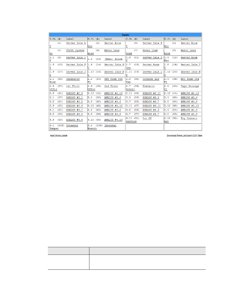
Figure 3.5
FMS Input Configuration Menu
Inputs and relays located on expansion cards are identified by their name and slot channel
number, referred to in the Inputs table as S.Ch. For example, an input with a S.Ch number of
1.9 is located on the expansion card in slot one, and is the 9th input on that card. An input with
a S.Ch number of 4.2 is located on the expansion card in slot 4, and is the 2nd input on that
card. If an input has no S.Ch number, that means it is located on the FMS’s main card.
Relays work the same way. A relay with no S.Ch number is located on the FMS’s main board.
A relay with an S.Ch number of 1.4 is located on the expansion card in slot 1, and is the 4th
relay on that card.
Clicking an input link will display one of three input configuration pages - each card has its
own configuration page. Only the options available for the particular inputs on the card will be
displayed.
Relay configuration works the same way. Click a relay link to display that relay’s
configuration information. Only the configuration options available for that particular relay
will appear.
You’ll notice a link placed between the Inputs and Relays tables:
Option
Description
Download Points
List Export CSV
Table
Click this link to view a CSV list of all the inputs configured on this
FMS unit.
Table 3.2
Inputs and Relays Configuration Page - Additional Link