Relay assignments – Super Systems 9130 Series User Manual
Page 38
Series 9130 Operations Manual Rev -
37
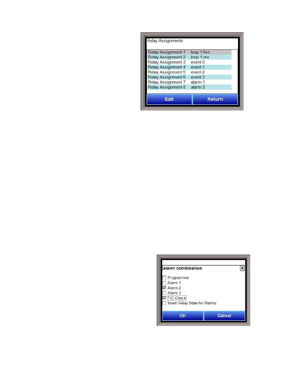
Relay Assignments
The 9130 controller has the option of using eight
relay outputs, as well as eight relay outputs for
four additional modules. All of the relays have a
positive common terminal and independent
negative terminals. All of the relays are configured
in a normally closed position except relay number
eight, which has both a normally closed (NC) and a
normally open (NO) terminal. These relays can be
configured to work with events, alarms, loops,
burnoff and alarm combinations.
Relay Output Terminals:
Relay Output 1 – terminals 7 and 8
Relay Output 2 – terminals 7 and 9
Relay Output 3 – terminals 7 and 10
Relay Output 4 – terminals 7 and 11
Relay Output 5 – terminals 7 and 12
Relay Output 6 – terminals 7 and 13
Relay Output 7 – terminals 7 and 14
Relay Output 8 – terminals 7 and 15 NC
Relay Output 8 – terminals 7 and 16 NO
Relay Output Choices
Loop 1 fwd
Event 6
Loop 1 rev
Event 7
Loop 2 fwd
Event 8
Loop 2 rev
Event 9
Loop 3 fwd
Event 10
Loop 3 rev
Event 11
Programmer Alarm
Event 12
Alarm 1
Event 13
Alarm 2
Event 14
Alarm 3
Event 15
Event 0
TC Redundancy Select (OFF = TC 1; ON = TC 2)
Event 1
PV Switching Select (OFF = PV 1; ON = PV 2)
Event 2
Timer Running
Event 3
Timer Complete
Event 4
Alarm Combination
Event 5
N/A
The “Alarm Combination” option will allow the user to
select the specific combination of alarms to use.
The options are: Programmer, Alarm 1, Alarm 2, Alarm 3,
T/C Check, or Invert Relay State for Alarms.
The Return button will return the user to the menu
screen.