Nalog, Nput, Etup – Super Systems 9130 Series User Manual
Page 79: Onfiguration and, Alibration, Overview, Equipment needed, Notes
Series 9130 Operations Manual Rev -
78
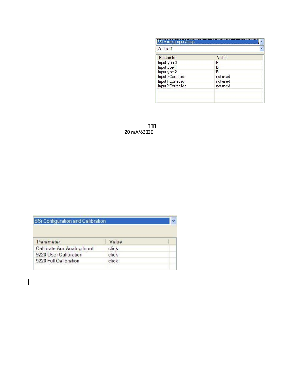
SSi Analog Input Setup
The SSi Analog Input Setup menu option allows the
user an input selection of three inputs per module, and
three input corrections per module. There are eight
modules available. It is configurable for voltage of T/C
(universal input), and it is typically used for Load T/Cs
and Auxiliary Flow Meters.
Input Type 0 – Input Type 2
This will select the input type for the module. The
options are:
B
NNM
160 mV
C
R
80 mV
E
S
40 mV
J
T
20 mV
25.6 volts**
K
2.56 volts
4-20 mA/124
12.8 volts**
N
1.28 volts
4-
** - When the specified input type is selected, a jumper located inside the case will need
to be placed on that specific input for reading this selection. If jumper is not placed on
input, then damage could occur to the board.
Input 0 Correction – Input 2 Correction
This option will set a correction curve for the input. The options for the input corrections are: not used,
Curve 1 – Curve 3.
Input 1 Open T/C – Input 3 Open T/C
This option will allow the user to set the direction of the open T/C for each input. The options are: Up Scale
or Down Scale.
SSi Configuration and Calibration
Overview
The series 9130 can be calibrated
using the operator interface
Configurator software usually
supplied with the system. Before
performing this procedure on a newly
installed controller, the unit needs to
be powered on for at least 30 minutes
for a warm up period.
The series 9130 has three analog
inputs. Each range has a zero and span calibration value. A cold junction trim value must be calibrated for
thermocouple inputs. There are two analog outputs each with a zero and span value.
Equipment needed
A certified calibrator(s) with the ability to input and read millivolts, milliamps and thermocouples is
required. The appropriate connection leads are also required. A 24VDC 75-watt power supply is required.
The operator interface method requires a PC with the Configurator software loaded. An Ethernet crossover
cable is required.
Notes
Input 1 – terminals 31 and 32
Input 2 – terminals 29 and 30