Analog output setup – Super Systems 9130 Series User Manual
Page 41
Series 9130 Operations Manual Rev -
40
Analog Output Setup
The 9130 controller has the option of two (2) analog
outputs. The outputs are ranged for a 4 – 20 milliamp
signal or a 0 – 20 milliamp signal. Each output comes
with a factory default configuration dependent on the
application. Each output can be modified prior to
shipment to your facility or in the field by a supervisor.
Analog Output Terminals
Analog output 1 – terminals 24 and 25
Analog output 2 – terminals 25 and 26
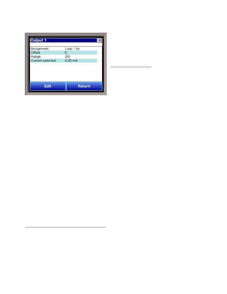
Assignment
The analog output assignment can be modified
depending on your system requirements. To change the
Assignment first select which analog output you want to
change by selecting it in the pull-down menu at the top of the screen. The following is a list of the options:
PV 1 retrans
Loop 3 dec
Loop 1 inc
Loop 3 combo
Loop 1 dec
Input 1 retrans
Loop 1 combo
Input 2 retrans
PV 2 retrans
Input 3 retrans
Loop 2 inc
SP1 retrans
Loop 2 dec
Programmer ID
Loop 2 combo
Disabled
Loop 3 inc
Offset
This is the starting point, the Process Variable value at which you get 4 milliamps. Clicking on this value
will display an input box from which the user can select a new value. The range is –32768 to 32767.
Range
This is a Process Variable value between 4 and 20 milliamps. Clicking on this value will display an input box
from which the user can select a new value. The range is –32768 to 32767.
Note - The range, although not displayed with a decimal point, contains a decimal point that is dependent
on the process variable selected. For example, if the offset is 20 mV for 4 mA, and you want 100 mV to be 20
mA, then your range should be 80. If the process variable is temperature, then the range will be 80, since
temperature PVs do not have a decimal. If the PV is % Carbon, then the range will need to include the two
decimal points for % Carbon. So, a range of 80 will be entered as 8000.
See below for more examples
.
Current Selection
Provides the option of 4-20 mA or 0-20 mA control. Clicking on this value will display an input box with a
drop-down list from which the user can select either of the two values listed above.
Offset and Range when assigned to a control loop
Inc : 0 = 4mA, 100 = 20mA
Dec : 0 = 4mA, -100 = 20mA
Example: if 4 – 20 mA = 800 mV - 1200 mV
Offset = 800 (starting point)
Range = 400
The Return button will return the user to the menu screen.