A/i module offset correction, Pv switching, Aux setpoint configuration – Super Systems 9130 Series User Manual
Page 54
Series 9130 Operations Manual Rev -
53
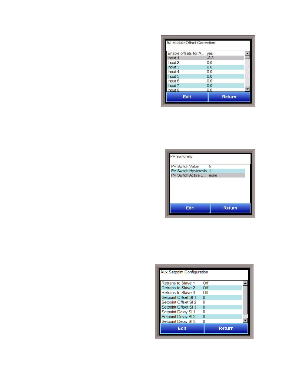
A/I Module Offset Correction
The Analog Input module offset correction menu option
gives the user the ability to offset any input on any A/I
module for up to forty (40) inputs. Input correction curves
can also be applied to inputs 1 through 40. The offset can
be in degrees + or -, and it is typically used to compensate
for incorrect T/C wires.
Enable Offsets for Aux AIB
This option will determine if the offsets entered will be
applied on the inputs. The options are: Yes or No.
Input 1 – Input 40
This will be the offest for the specified input. The range of
the offsets is –50.0 to 50.0.
Input 1 Correction – Input 40 Correction
This will allow the user to enter a correction curve, if desired, to inputs 1 through 40. The options are: Not
Used, Curve 1 – Curve 3.
PV Switching
PV Switching allows the 9130 to use two (2) analog inputs as a
process variable source, if necessary. It can be customized
in any combination of high or low signals for loops 1, 2, or 3.
The 9130 controller normally only uses loop 1 for
temperature control, so PID loop 2 or 3 must be modified so
that it has a control source. In order for the PV signal to be
switched,
both
PV signals must be above or below the switch
point and must satisfy any applicable hysteresis.
PV Switch Value
This is the switch value. This is the value that will determine
when the switch happens. The range is -300 – 30000.
PV Switch Hysteresis
This is the hysteresis for the switch. This will help prevent the 910 from potentially switching back and
forth between the two signals. The range is 0 – 30000.
PV Switch Active Loop
This field is not modifiable. It will display the current active loop (Loop 1 – Loop 3).
Aux Setpoint Configuration
Aux Set Point Configuration is an automatic set point
retransmission with a corresponding custom offset and
delay to one or more of the first 3 configured slave
instruments. The delay is in minutes and is only active
when the set point is dropped. This feature would most
commonly be used to keep the alarm set point of an
overtemp tracking the furnace's main set point (with
offset). The delay allows the furnace time to cool below
the level specified so that there is no overtemp alarm
when the furnace is cooling.