Nstrument, Alculation – Super Systems 9130 Series User Manual
Page 90
Series 9130 Operations Manual Rev -
89
Digital IN2 is Timer Reset/Ack
This option will determine if the Digital Input 2 reset/acknowledge option is available. The options are
Enabled (checked) or Disabled (Unchecked).
Target Time
This option will set the initial starting setpoint for the timer. The “Hour” option can range from 0 to 32767.
The “Minute” option can range from 0 to 59.
Relay ON Time (Sec)
This option will determine how long to wait before turning a relay on. The range is entered in seconds, and
goes from -32768 to 32767.
Start Band
This option will determine the initial deviation band that will allow the timer to start. The range is -32768 to
32767.
Run Band
This option will determine the deviation band that will keep the timer running. The range is -32768 to
32767.
Standby Set Point
This option will set the standby setpoint for the timer. The range is -32768 to 32767.
Idle Output
This option will determine the idle output time. The range is -32768 to 32767.
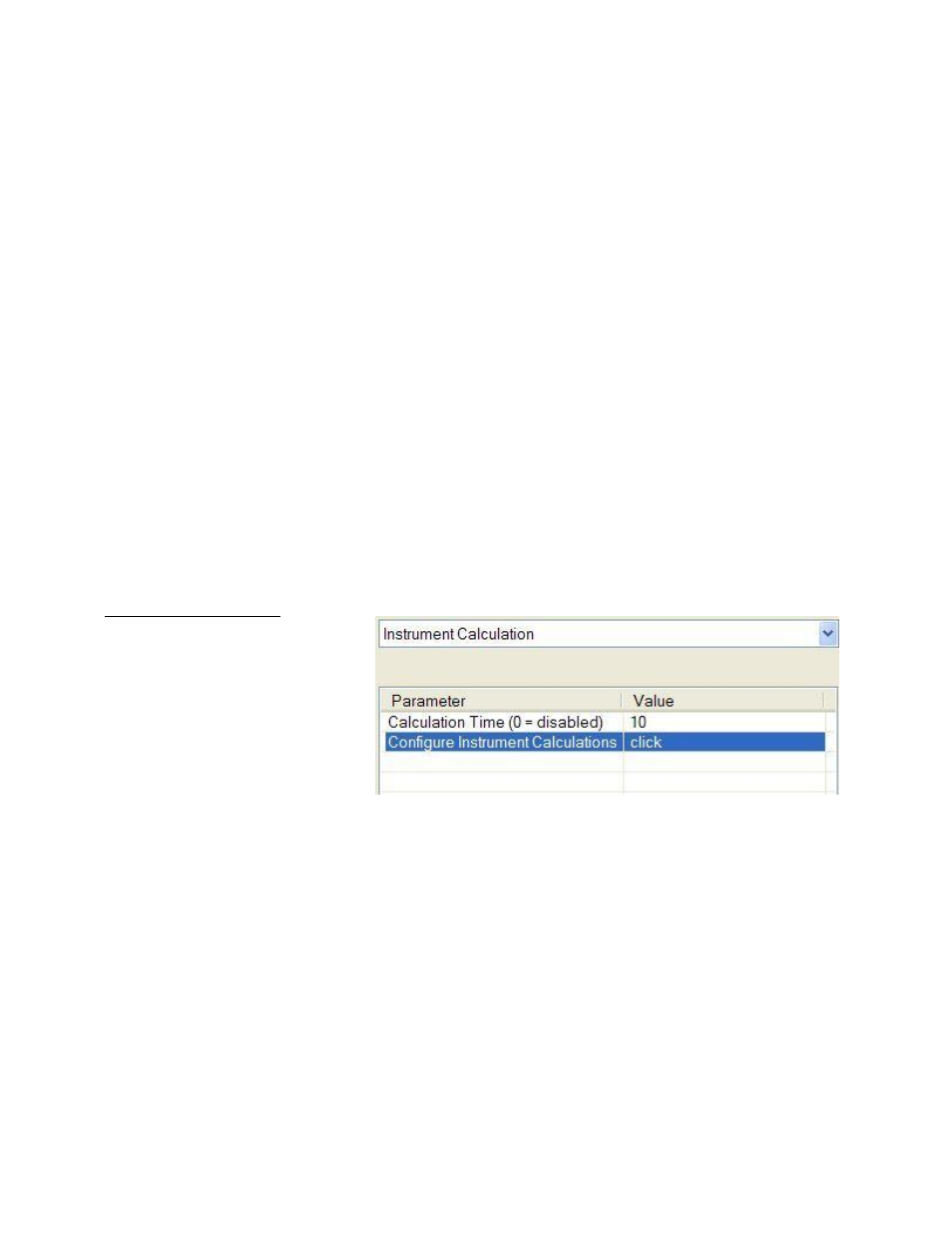
Instrument Calculation
The Instrument Calculation menu
allows programming code-like lines
to be executed at a variable time
interval per step.
Note – It is
important to contact Super Systems
at 800-666-4330 before creating or
modifying any Instrument
Calculation customization
.
General Description
The Instrument Calculation allows for fifty (50) lines of program and fifty (50) program variables. Program
variables allow for storage on intermediate results of calculations.
A program variable is designated by a v followed by a number from 0 to the number of variables – 1.
A Lower or Upper case “V” is valid, as well as leading zeroes. The following are all considered the same
variable: V3, v3, v0003.
The 9220’s Modbus registers can be used as input variables in the equations without restriction. To protect
the instrument, Modbus registers are restricted as output registers.
Modbus registers are designated by an upper or lower case “M” followed by a number.
Note – The standard Modbus routine is called to retrieve the Modbus variable, therefore a 0x8000 (-32768)
will be returned for an invalid register
.
Note – Modbus registers are stored with integer values, so adjustments will need to be made for decimal
values
.
If the instrument can have external analog input boards, or the instrument is a Video Recorder or DAQ,
these inputs can be accessed directly as A1 through A40. By using the “A” designation, the Modbus register
number is not needed and the variable is scaled to the correct value (decimals included) based on the input
type specified.