Nonlinear axis error compensation, 4 nonlinear axis error compensation – HEIDENHAIN TNC 335 Technical Manual User Manual
Page 121
4-24
TNC 360
1 Machine Axes
8/95
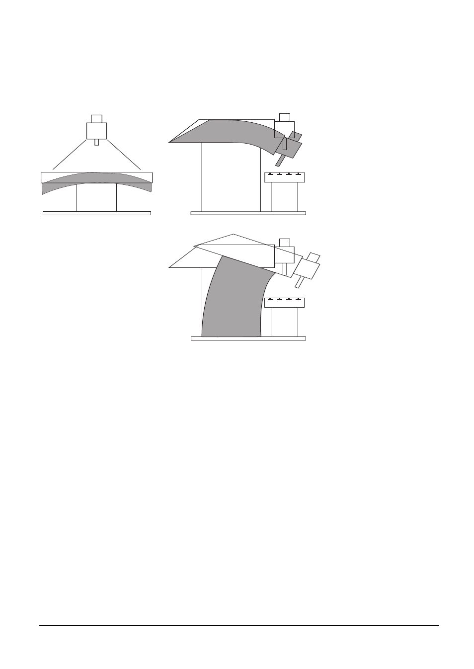
1.6.4 Nonlinear axis error compensation
Depending on the design of the machine or external factors (e.g. temperature) a nonlinear axis-error
can occur.
Such an axis-error is usually determined by a comparator measuring instrument (e.g. HEIDENHAIN
VM 101A).
For example, the leadscrew pitch error for the Z axis (Z=F(Z)) or the sag as a function of the Y axis
(Z=F(Y)) could be determined.
In the HEIDENHAIN contouring control an axis can only be corrected as a function of one error-
related axis. So in our example either the leadscrew pitch or the sag can be compensated. For each
of the four axes one table of corrections with 64 correction values per table can be entered. The
following definitions must be fixed for this purpose:
Correlation:
Correction as a function of which axis?
(X=F(X); X=F(Y) etc.)
Datum point:
Distance to the machine datum
The error curve must always start with
correction value = 0 at the datum point.
Distance:
Distance between the correction points (grid).
entry of the exponent to base 2
(e.g. entry 11 = 2
11
= 2,048 mm).
max. input value = 2
23
When determining the error curve with the aid of a comparator measuring instrument the above
definitions must be already taken into account, whereby it is important to note that the error curve is
continued in positive direction starting at the datum.