Summary of connections, 3 summary of connections – HEIDENHAIN TNC 335 Technical Manual User Manual
Page 42
3-12
TNC 360
3 Summary of Connections
8/95
3 Summary of Connections
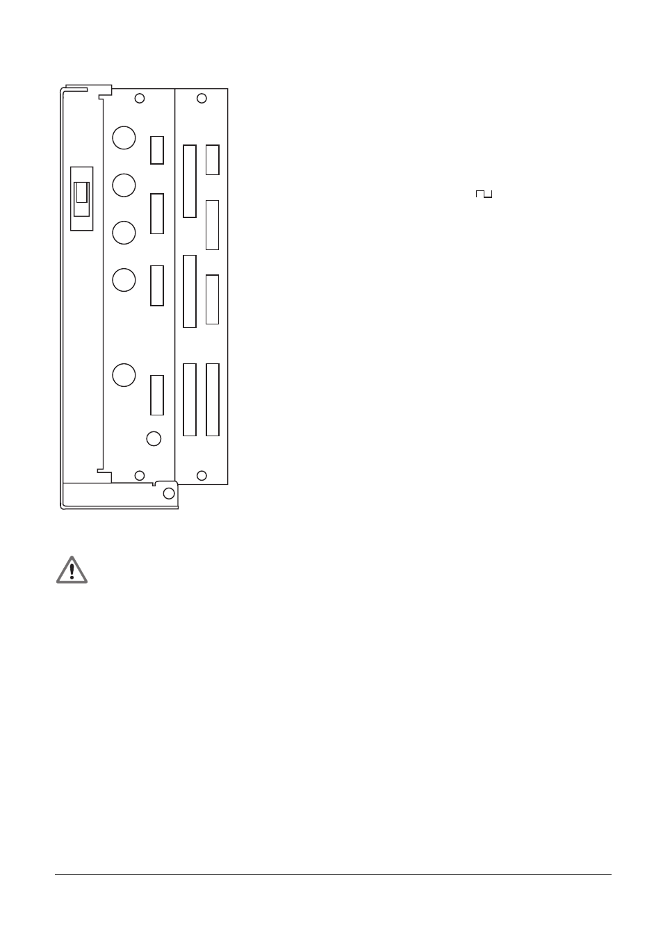
X1
X2
X3
X4
X6
X11
X12
X8
B
X24
24V
X31
X9
X21
X22
X23 X27
X26
X25
Control loop board
X1 = Measuring system 1 (~)
X2 = Measuring system 2 (~)
X3 = Measuring system 3 (~)
X4 = Measuring system 4 (~)
X5 = Measuring system 5 (~)
X6 = Measuring system S (
)
X12 = Touch probe system
X8 = Nominal value outputs 1,2,3,4,S
X9 = VDU
X11 = HR 130/330/332 handwheels,
HRA 110
PLC and graphics board
X21 = PLC output
X22 = PLC input
X23 = TNC keyboard (TE)
X24 = Power supply 24 V for PLC
X25 = Data interface RS-232-C/V.24
X26 = Input/Output board PL 410
X27 = Machine operating panel
X31 = Power supply 24 V for NC
B
= Signal ground
Danger to internal components!
Do not engage or disengage any connections while the unit is under power.