4 ) i/o data settings – Yaskawa MP2000 Series I/O Module User Manual User Manual
Page 106
4.3 LIO-06 Module Details
4.3.3 Counter Module Configuration
106
* 1. For details, refer to 4.4.1 Pulse Counting Modes on page 111.
* 2. For details, refer to 4.4.3 Coincidence Output and Coincidence Interrupt Functions on page 114.
* 3. For details, refer to 4.4.5 Axis Type Selection on page 116.
* 4. For details, refer to 4.5 Electronic Gear Function on page 117.
* 5. If pulse is selected for the parameter No. 08, parameters No. 10 to 12 are ignored.
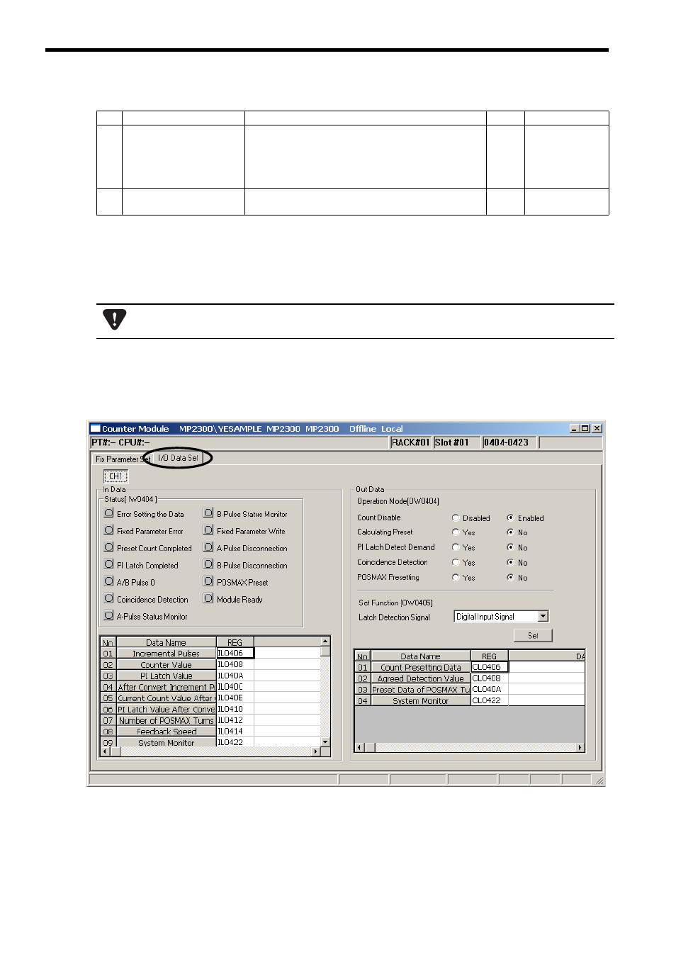
( 4 ) I/O Data Settings
[ a ] I/O Data Setting Tab Page
Set the I/O data in the I/O Data Set Tab Page in the Counter Module Window.
The channel number is fixed to CH1.
The details on the status and I/O data that can be monitored in the I/O Data Set Tab Page are described below.
14
Encoder Resolution
(Pre Quadrature)
(Number of Pulses Per
Encoder Rotation
(before Multiplication))
Set the number of input pulses per encoder rotation.
Setting range: 1 to 2147483647 (pulse/rev)
2 words
2048
15
Detection of A/B-pulse
Disconnection
Select whether or not the phase A/B disconnection detection
is enabled or not.
1 word
disable
(cont’d)
No.
Name
Description
Size
Default
If SYNC-SCAN (Synchronous Scan Selection) is changed, be sure to save the data in the flash memory and
restart the controller.