2 ) cn2 connector – Yaskawa MP2000 Series I/O Module User Manual User Manual
Page 77
3.2 Specifications of LIO-04/LIO-05 Module Connections
3.2.5 LIO-04 Module Connections
77
3
LIO-04/LIO-05 Module
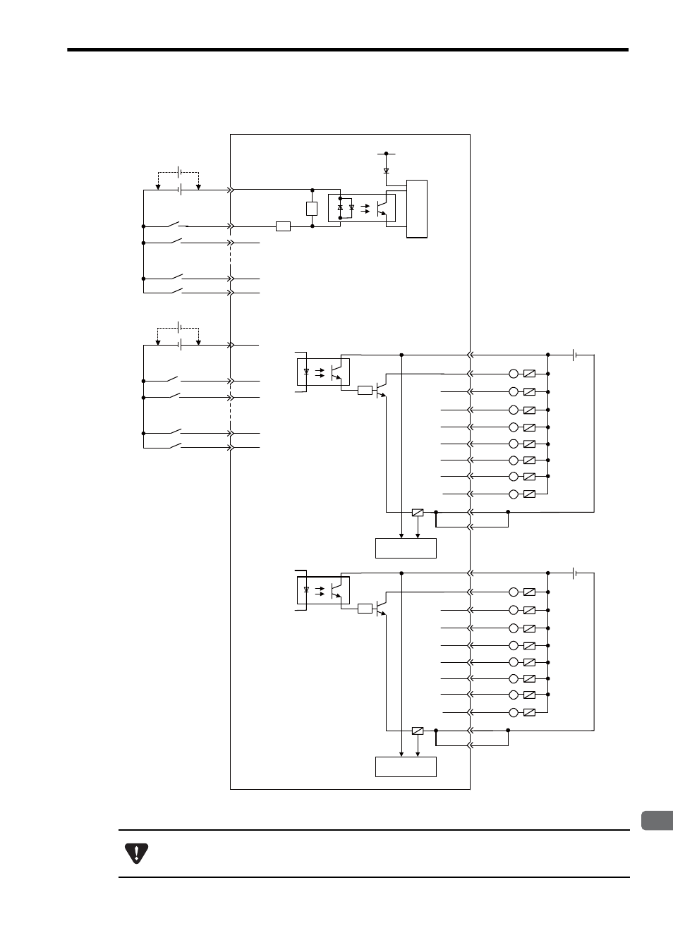
( 2 ) CN2 Connector
The pins No. 39 and 43 and the pins No. 46 and 50 are internally connected. Connect them externally as well.
2303
JAPMC-IO
+5V
+
-
+
-
+ -
+
-
6
7
32
10
35
1
2
27
5
30
Internal
circuit
5.6k
ǡ
R
R
38
12
13
41
17
42
16
L
L
L
L
L
+ -
43
37
L
39
15
R
L
L
45
19
20
48
24
49
23
L
L
L
L
L
+ -
50
44
L
46
22
R
L
L
Photocoupler
Photocoupler
Photocoupler
Input 16
Input 17
Input 22
Input 23
24 VDC
24 VDC
Com-
mon 3
Com-
mon 4
Input 24
Input 25
Input 30
Input 31
CN2 connector
pin No.
Fuse blown
detection circuit
Fuse blown
detection circuit
Output 17
Output 16
Output 18
Output 19
Output 21
Output 22
Output 23
Output 24
Output 20
24 VDC
24 VDC
Output 25
Output 26
Output 27
Output 29
Output 30
Output 31
Output 28
A fuse is inserted in the output common line of the LIO-04 Module for circuit protection. However, the fuse
may not be blown out in the cases such as layer shorts in outputs. To ensecure the circuit protection, provide
a protective element such as fuse in each output as shown in the above diagram.