4 led indicators and switch settings – Yaskawa MP2000 Series I/O Module User Manual User Manual
Page 33
2.1 Outline of LIO-01/LIO-02 Modules
2.1.4 LED Indicators and Switch Settings
33
2
LIO-01/LIO-02 Module
2.1.4 LED Indicators and Switch Settings
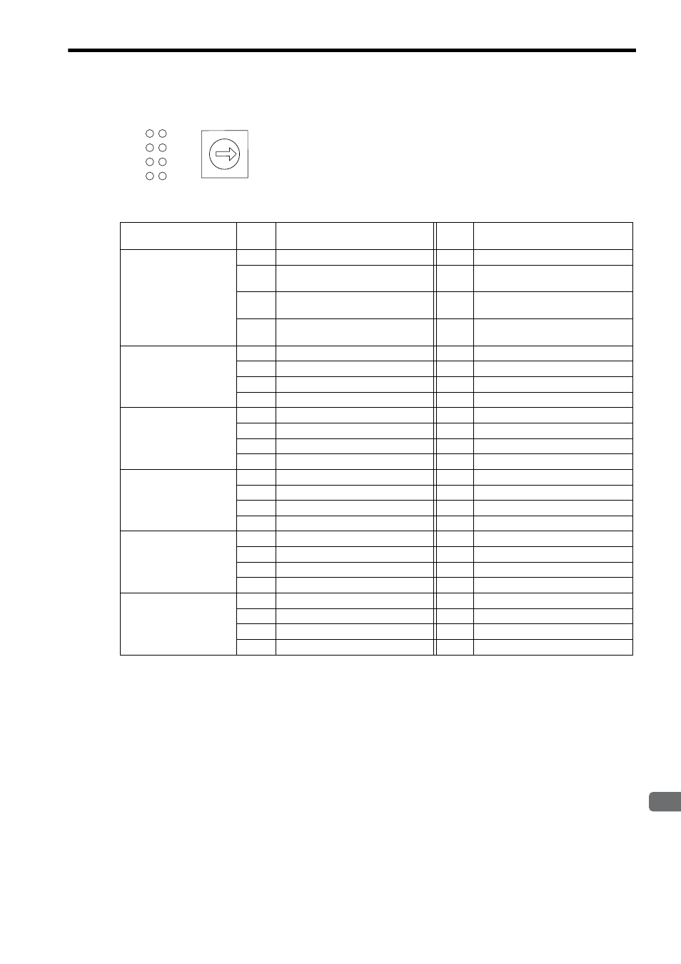
The LIO-01 and LIO-02 Module status display LED indicators (LD1 to LD8)
change based on the SW1 rotary switch settings (setting range: 0 to 5). The fol-
lowing table shows the indicator display for DI and DO status according to the
SW1 setting.
SW1 (Rotary Switch)
Set Value
LD No.
Status When Lit (Green)
LD No.
Status When Lit (Green)
0
(Board Status Indicator)
LD1
Normal (Error when not lit)
LD5
Normal (Error when not lit)
LD2
One of the inputs D1_00 to DI_07 is
ON.
LD6
One of the inputs DI_08 to DI_15 is
ON.
LD3
One of the outputs DO_00 to DO_07
is ON.
LD7
One of the outputs DO_08 to DO_15
is ON.
LD4
Pulse A/B input. The Phase A/B is
ON.
LD8
Pulse Z input. The Phase Z is ON.
1
(DI Input Indicator 1)
LD1
DI_00 is ON.
LD5
DI_04 is ON.
LD2
DI_01 is ON.
LD6
DI_05 is ON.
LD3
DI_02 is ON.
LD7
DI_06 is ON.
LD4
DI_03 is ON.
LD8
DI_07 is ON.
2
(DI Input Indicator 2)
LD1
DI_08 is ON.
LD5
DI_12 is ON.
LD2
DI_09 is ON.
LD6
DI_13 is ON.
LD3
DI_10 is ON.
LD7
DI_14 is ON.
LD4
DI_11 is ON.
LD8
DI_15 is ON.
3
(DO Output Indicator 1)
LD1
DO_00 is ON.
LD5
DO_04 is ON.
LD2
DO_01 is ON.
LD6
DO_05 is ON.
LD3
DO_02 is ON.
LD7
DO_06 is ON.
LD4
DO_03 is ON.
LD8
DO_07 is ON.
4
(DO Output Indicator 2)
LD1
DO_08 is ON.
LD5
DO_12 is ON.
LD2
DO_09 is ON.
LD6
DO_13 is ON.
LD3
DO_10 is ON.
LD7
DO_14 is ON.
LD4
DO_11 is ON.
LD8
DO_15 is ON.
5
(PI Input Indicator)
LD1
Pulse A input
LD5
Coincidence detection
LD2
Pulse B input
LD6
Phase-Z latch
LD3
Pulse Z input
LD7
DI latch
LD4
–
LD8
–
LD3
LD2
LD1
LD4
LD7
LD6
LD5
LD8
Indicators
SW1
0
5
1
2
3
4
6
7
8
9