4 details of counter functions – Yaskawa MP2000 Series I/O Module User Manual User Manual
Page 52
2.4 Details of Counter Functions
2.3.2 Counter Module Configuration
52
2.4 Details of Counter Functions
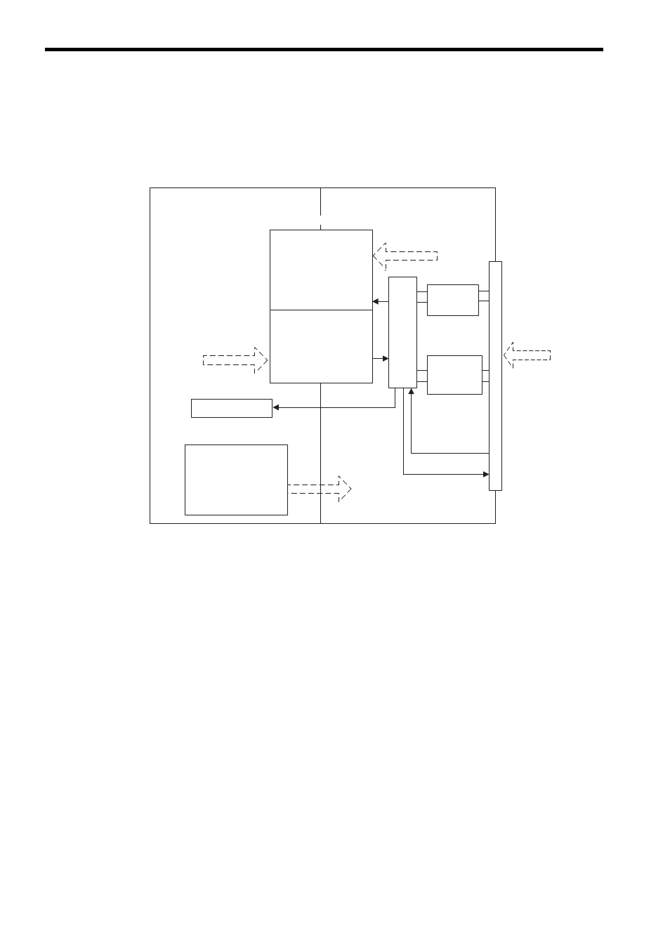
For the counter function, the command is determined according to the settings of the counter fixed parameters and out-
put registers, and the status and counter value are stored in input registers.
The following diagram shows the data flow for the counter function.
In this section, the fixed parameters mean the counter fixed parameters if not otherwise mentioned.
Refer to 1.3 Self-configuration on page 23 to execute self-configuration of the Machine Controller before set-
ting the fixed parameters.
The following describes the details of pulse counting modes, pulse count function, coincidence output and coincidence
interrupt functions, and PI latch function among the counter functions of the LIO-01 or LIO-02 Modules.
᧦ઙ⸳ቯ
MP2000 Series Machine Controller
Coincidence
interrupt
Commands from MP2000 Series
Machine Controller
to LIO-01 or LIO-02 Module
Counter Fixed Parameters
Interrupt
processing section
Condition settings
for counter function
use
Pulse A/B signal polarity
ޓselection
Pulse counting mode
Other function selections
Input Registers (32 words)
Operation status
Incremental pulse
Current counter value
Latch data, etc.
Output registers (32 words)
Operation mode
Counting preset data
Coincidence
ޓdetection setting, etc.
Pulse input
processo
r
Latch input DI-01
Coincidence detection
output DO-00
Phase-Z 5-V/
12-V voltage
interface
5-V
differential
interface
I/O
connector
Pulse input
Information to MP2000 Series
Machine Controller from
LIO-01 or LIO-02 Module
LIO-01 or LIO-02 Module
Virtual shared memory