6 lio-01/lio-02 module connections, 1 ) lio-01 module connectors, Lio-01/lio-02 module – Yaskawa MP2000 Series I/O Module User Manual User Manual
Page 39
2.2 Specifications of LIO-01/LIO-02 Module Connections
2.2.6 LIO-01/LIO-02 Module Connections
39
2
LIO-01/LIO-02 Module
2.2.6 LIO-01/LIO-02 Module Connections
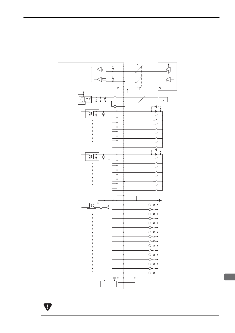
The following diagrams show connection examples for LIO-01/LIO-02 Module connectors.
( 1 ) LIO-01 Module Connectors
The pins No. A5 and B5, and the pins No. A6 and B6 are internally connected. Connect them externally as well.
+5V
0V
+5V
5V
A2
B2
A4
PB
PBL
GND
PC
PCL5
PCL12
A3
A24
B24
B3
B4
PA
PAL
A1
B1
DI_COM0
DI_01
DI_02
DI_03
DI_04
DI_05
DI_06
DI_07
DI_00
A23
B22
A22
B21
A21
B20
A20
B19
A19
24 VDC
R
R
DI_COM1
DI_09
DI_10
DI_11
DI_12
DI_13
DI_14
DI_15
DI_08
B23
B18
A18
B17
A17
B16
A16
B15
A15
24 VDC
R
R
R
R
R
R
R
Fuse
L
L
L
L
L
L
L
L
L
L
L
L
L
L
L
L
24 VDC
DO_00
DO_01
DO_02
DO_03
DO_04
DO_05
DO_06
DO_24V
DO_07
DO_08
DO_09
DO_10
DO_11
DO_12
DO_13
DO_14
DO_15
DO_COM
DO_COM
B6
A6
B14
A14
B13
A13
B12
A12
B11
A11
B10
A10
B9
A9
B8
A8
B7
A7
A5
B5
R
Pulse input
Latch input
or phase-Z
pulse
Digital input
Digital input
Digital output
Fuse blown
detection circuit
Fuse
Pulse Generator
Phase A
Latch input or phase-Z pulse
External input signals
External input signals
External output signals
A fuse is inserted in the output common line of the LIO-01 Module for circuit protection. However, the fuse
may not be blown out in the cases such as layer shorts in outputs. To ensecure the circuit protection, pro-
vide a protective element such as fuse in each output as shown in the above diagram.