5 pulse input circuit – Yaskawa MP2000 Series I/O Module User Manual User Manual
Page 38
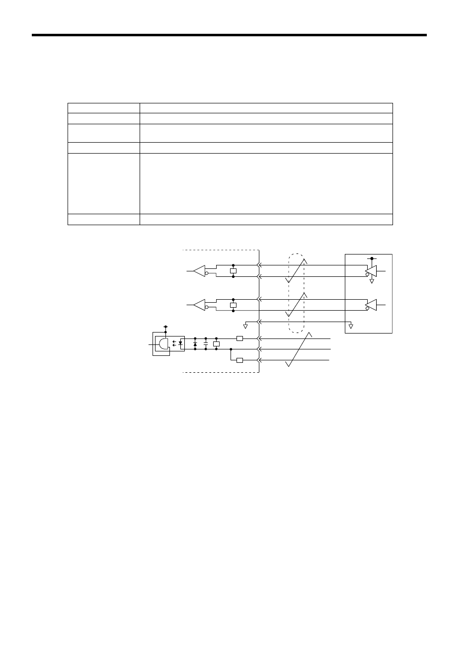
2.2 Specifications of LIO-01/LIO-02 Module Connections
2.2.5 Pulse Input Circuit
38
2.2.5 Pulse Input Circuit
The following table shows the LIO-01/LIO-02 Module pulse input circuit specifications.
Fig. 2.6 Pulse Input Circuit
Item
Specifications
Number of Channels
1 channel (Phase-A/B/Z input)
Input Circuit
Phase-AB: 5-V differential input, not isolated, max. frequency: 4 MHz
Phase-Z: 5-V/12-V photocoupler input
Input Mode
Phase-A/B, signed, incremental/decremental
Latch Input
Pulse latch on phase-Z or DI_01.
Response time at phase-Z input
ON: 1
μs max.
OFF: 1
μs max.
Response time at DI_01 input
ON: 60
μs max.
OFF: 0.5 ms max.
Other Functions
Coincidence detection, counter preset
+5V
0V
Phase B
Phase A
A1
Pulse Generator
PA
PAL
PB
PBL
GND
B1
A2
B2
B3
B4
A4
A3
+5V
Latch input or
phase-Z pulse
PC
PCL5
PCL12
R
R
R
R
R