2 ) cn2 connector – Yaskawa MP2000 Series I/O Module User Manual User Manual
Page 132
5.2 Specifications of DO-01 Module Connections
5.2.4 DO-01 Module Connections
132
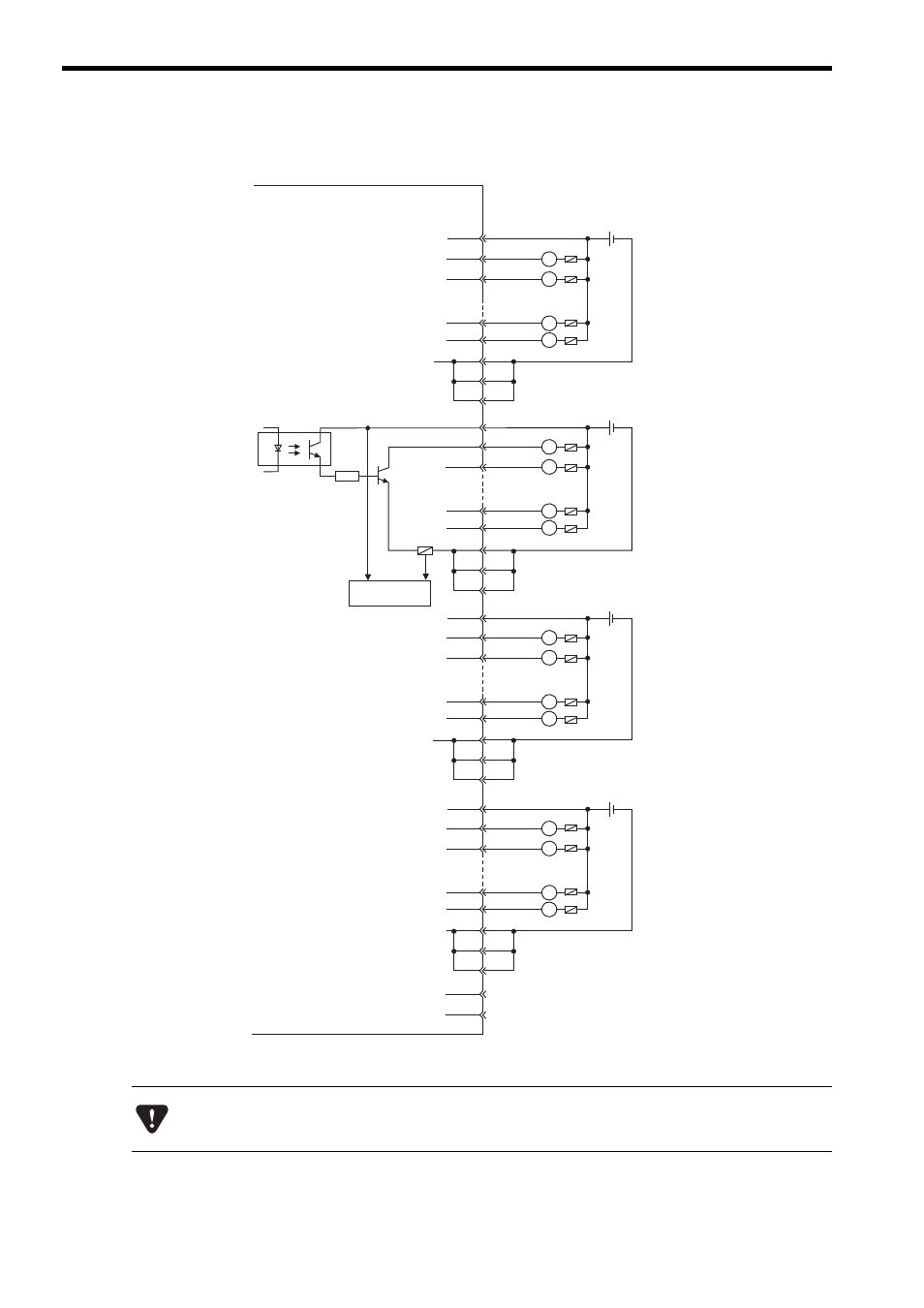
( 2 ) CN2 Connector
The pins No. 6, 26, and 31, the pins No. 12, 32, and 37, the pins No. 18, 38, and 43, and the pins No. 24, 44, and 49
are internally connected. Connect them externally as well.
7
8
33
11
36
13
12
14
39
17
42
18
19
20
45
23
48
24
25
50
1
2
27
5
30
6
31
26
䊶
䊶
䊶
䊶
䊶
䊶
䊶
䊶
䊶
䊶
䊶
䊶
+ -
L
L
L
L
+ -
L
L
L
L
+ -
L
L
L
L
+ -
L
L
L
L
JAPMC-DO2300
㪝㫌㫊㪼
R
37
32
43
38
49
44
Photocoupler
Fuse blown
detection circuit
Fuse
CN2 connector
pin No.
Output 33
Output 32
Output 39
Output 38
24 VDC
24 VDC
Output 41
Output 40
Output 47
Output 46
Output 49
24 VDC
Output 48
Output 55
Output 54
Output 57
24 VDC
Output 56
Output 63
Output 62
A fuse is inserted in the output common line of the DO-01 Module for circuit protection. However, the fuse
may not be blown out in the cases such as layer shorts in outputs. To ensecure the circuit protection, provide
a protective element such as fuse in each output as shown in the above diagram.