4 do-01 module connections, 1 ) cn1 connector – Yaskawa MP2000 Series I/O Module User Manual User Manual
Page 130
5.2 Specifications of DO-01 Module Connections
5.2.4 DO-01 Module Connections
130
5.2.4 DO-01 Module Connections
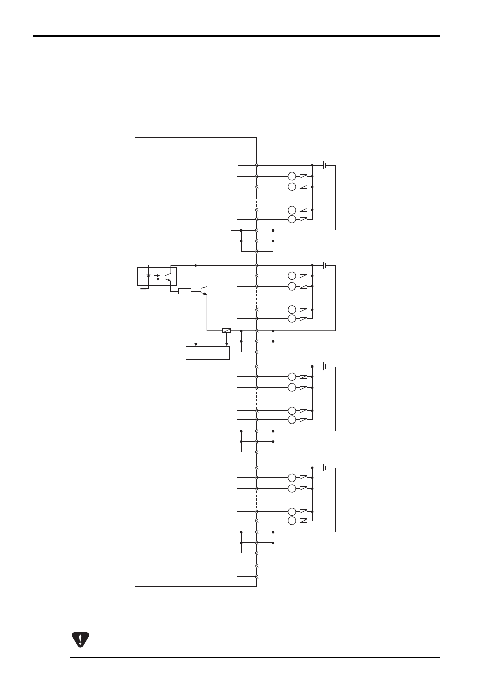
The following diagrams show connection examples for CN1/CN2 connector of the DO-01 Module.
( 1 ) CN1 Connector
The pins No. 6, 26, and 31, the pins 12, 32, and 37, the pins 18, 38, and 43, and the pins No. 24, 44, and 49 are
internally connected. Connect them externally as well.
7
8
33
11
36
13
12
14
39
17
42
18
19
20
45
23
48
24
25
50
1
2
27
5
30
6
31
26
䊶
䊶
䊶
䊶
䊶
䊶
䊶
䊶
䊶
䊶
䊶
䊶
+ -
L
L
L
L
+ -
L
L
L
L
+ -
L
L
L
L
+ -
L
L
L
L
JAPMC-DO2300
R
37
32
43
38
49
44
Photocoupler
Fuse blown
detection circuit
Fuse
CN1 connector
pin No.
Output 1
Output 0
Output 6
24 VDC
Output 7
Fuse
Output 9
24 VDC
Output 8
Output 15
Output 14
Output 17
24 VDC
Output 16
Output 23
Output 22
Output 25
24 VDC
Output 24
Output 31
Output 30
A fuse is inserted in the output common line of the DO-01 Module for circuit protection. However, the fuse
may not be blown out in the cases such as layer shorts in outputs. To ensecure the circuit protection, provide
a protective element such as fuse in each output as shown in the above diagram.