1 connector specifications – Yaskawa MP2000 Series I/O Module User Manual User Manual
Page 34
2.2 Specifications of LIO-01/LIO-02 Module Connections
2.2.1 Connector Specifications
34
2.2 Specifications of LIO-01/LIO-02 Module Connections
2.2.1 Connector Specifications
The LIO-01/LIO-02 Module connector connects the external I/O signals or pulse input signal. (External input: 16
points, external output: 16 points, pulse input: 1 channel)
The following tables provide the specifications of the LIO-01/LIO-02 Module connector.
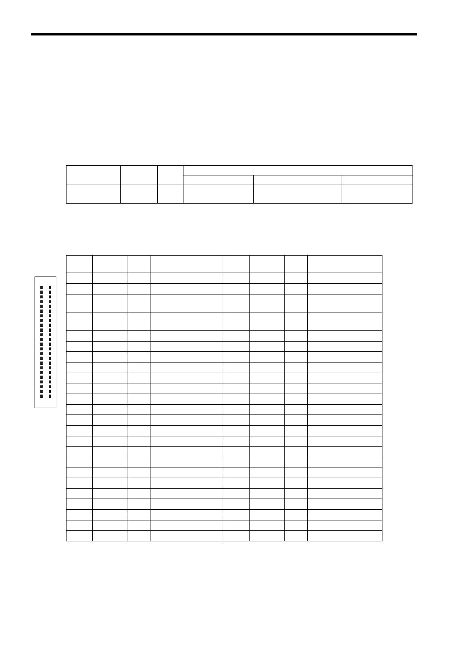
( 1 ) Connector Model
( 2 ) Connector Pin Arrangement
The following table shows the connector pin arrangement for LIO-01/LIO-02 Modules viewed from the wiring side
and the details of the pins.
Name
Connector
Name
No. of
Pins
Connector Model
Module Side
Cable Side
Manufacturer
I/O Connector
I/O
48
FCN-365P048-AU
FCN-360C048-E (cover),
FCN-361J048-AU
Fujitsu
component
Pin No.
Signal
Name
I/O
Remarks
Pin No.
Signal
Name
I/O
Remarks
A1
PA
I
Phase-A pulse (+)
B1
PAL
I
Phase-A pulse (
−)
A2
PB
I
Phase-B pulse (+)
B2
PBL
I
Phase-B pulse (
−)
A3
PC
I
Phase-Z pulse (+)
B3
PCL5
I
Phase-Z pulse
(
−5-V input)
A4
GND
I
Pulse input ground
B4
PCL12
I
Phase-Z pulse
(
−12-V input)
A5
DO_COM
P
Output common
B5
DO_COM
P
Output common
A6
DO_24V
P
+24 V input
B6
DO_24V
P
+24 V input
A7
DO_15
O
Output 15
B7
DO_14
O
Output 14
A8
DO_13
O
Output 13
B8
DO_12
O
Output 12
A9
DO_11
O
Output 11
B9
DO_10
O
Output 10
A10
DO_09
O
Output 9
B10
DO_08
O
Output 8
A11
DO_07
O
Output 7
B11
DO_06
O
Output 6
A12
DO_05
O
Output 5
B12
DO_04
O
Output 4
A13
DO_03
O
Output 3
B13
DO_02
O
Output 2
A14
DO_01
O
Output 1
B14
DO_00
O
Output 0
A15
DI_15
I
Input 15
B15
DI_14
I
Input 14
A16
DI_13
I
Input 13
B16
DI_12
I
Input 12
A17
DI_11
I
Input 11
B17
DI_10
I
Input 10
A18
DI_09
I
Input 9
B18
DI_08
I
Input 8
A19
DI_07
I
Input 7
B19
DI_06
I
Input 6
A20
DI_05
I
Input 5
B20
DI_04
I
Input 4
A21
DI_03
I
Input 3
B21
DI_02
I
Input 2
A22
DI_01
I
Input 1
B22
DI_00
I
Input 0
A23
DI_COM0
P
Input common 0
B23
DI_COM1
P
Input common 1
A24
FG
Frame ground
B24
FG
Frame ground
P: Power supply input; I: Input signal; O: Output signal
B1
A1
B24
A24