4 ) i/o data settings – Yaskawa MP2000 Series I/O Module User Manual User Manual
Page 49
2.3 LIO-01/LIO-02 Module Details
2.3.2 Counter Module Configuration
49
2
LIO-01/LIO-02 Module
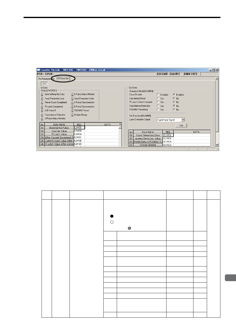
( 4 ) I/O Data Settings
[ a ] I/O Data Setting Tab Page
Set the I/O data in the I/O Data Set Tab Page in the Counter Module Window.
The channel number is fixed to CH1.
The details on the status and I/O data that can be monitored in the I/O Data Set Tab Page are described below.
[ b ] In (Input) Data Details
The following table provides details of the In Data Area.
Abbreviated names are given in square brackets in the Name column.
No.
Register
No.
Name
Contents
Range
Unit
Size
–
IW00
*1
Status
(Run Status)
[RUNSTS]
The run status of the Counter Module is
indicated for each bit.
When online:
: ON ( = 1 ),
: OFF ( = 0 ),
When off line:
–
–
1 word
Bit 0
Error Setting the Data
(Data setting error)
–
–
Bit 1
Fixed Parameter Error
–
–
Bit 2
Preset Count Completed
–
–
Bit 3
PI Latch Completed
–
–
Bit 4
A/B Pulse 0
(Feedback pulse is ±1 or less)
–
–
Bit 5
Coincidence Detection
–
–
Bit 6
A-Pulse Status Monitor
–
–
Bit 7
B-Pulse Status Monitor
–
–
Bit 9
Fixed Parameter Write
–
–
Bit A
A-Pulse Disconnection
–
–
Bit B
B-Pulse Disconnection
–
–
Bit C
POSMAX Preset
(POSMAX turns presetting
completed)
–
–
Bit F
Module Ready
–
–